![]()
Fan power is a significant consumer of energy in buildings. For example, in the building energy efficiency survey of non-domestic stock for England and Wales in 2014-15,1 the energy consumed by fans was estimated at more than 6GWh per year. To put this into context, this compares with the 5.4GWh used for space cooling and humidification, and amounts to more than 7% of electrical energy use in the non-domestic stock.
The survey report noted that the energy consumption for fans was most significant in sectors with long hours of use – including healthcare and emergency services – or where there was a need for extract ventilation to deal with catering odours and heat gain, such as those serving community centres, and arts, leisure and hospitality facilities.
The efficiency of a fan that is employed to move air in ventilation and air conditioning systems is commonly expressed in one of two ways – impeller efficiency and total fan efficiency.
Impeller efficiency relates to the mechanical power transferred to the impeller shaft and might, for example, be used when choosing a suitable motor; this provides the data that is typically represented in fan-efficiency curves. This efficiency is useful to provide a general indication of performance, but will reduce when the fan is installed, because of its relationship with the immediate elements of the ventilation system, as discussed later.
The total fan efficiency is often used to describe efficiency in terms of the electrical power for the whole fan system that is drawn from the mains electrical supply. This includes the power consumed by the motor control (such as the frequency converter), motor, and any intermediate drive chain elements, such as belt drive and shaft bearings, to provide the motive force to the impeller. The total efficiency may be determined at any operating condition from the air power (as described in the panel, ‘Air power’) divided by the power drawn from the electrical supply.
Total (installed) fan efficiency = air power (W)/total electrical input power (W)
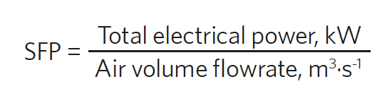
The SFP is a standardised measure of how much total power is required by the fan to move air through the connected system, and is expressed variously as W·L-1·s-1, kW·m-3·s-1 or (increased by 1,000) as W·m-3·s-1.
The standard BS EN 16798-3:2017 Energy performance of buildings – ventilation for buildings – Part 3: for non-residential buildings provides extensive and accessible information on the determination of SFP.
By setting, and implementing, a target maximum SFP (as, for example, in the UK and European regulations), it is possible to impose a standardised limit to the power requirements of ventilation systems. Reducing the SFP requires consideration not only of the fan, with its drive mechanics and control, but also its connection to the system and components of the ductwork installation. This considers the total pressure and will include frictional resistance (in terms of static pressure losses), velocity pressure ‘losses’ at entry and exit to the system and, importantly, the losses resulting from the ‘system effect’ or fan installation.
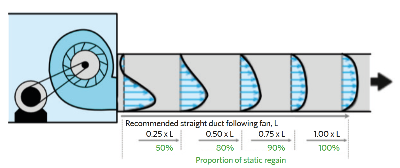
Figure 1: Typical velocity profiles and proportion of potential static regain in air leaving a housed centrifugal fan. The length of blue arrows indicates air velocity and illustrates that a uniform and steady profile does not develop until some distance away from the outlet (Based on data from AIVC Technical Note 652)
As illustrated in the example of a centrifugal fan in Figure 1, the velocity profile of air leaving the fan will take some distance to evolve into a spin-free, symmetrical, fully developed velocity profile. The uninterrupted straight duct length should be at least two and a half times the hydraulic diameter (hydraulic diameter = 4 x cross-sectional area of the outlet divided by the outlet perimeter), and preferably more than six diameters, depending on speed.3 This allows the asymmetric velocity profile at the outlet to develop as the initial high-velocity pressure converts to static pressure (known as ‘static regain’).
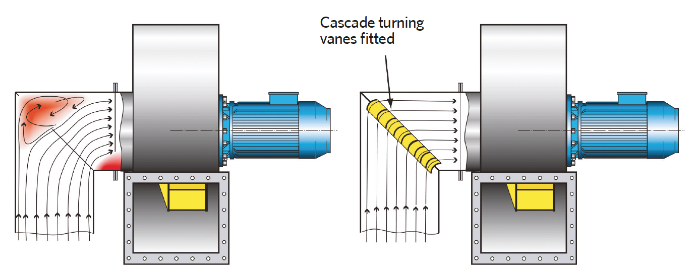
Figure 2: Adding turning vanes to minimise the impact of the bend that would otherwise adversely impact the fan performance (Source: CIBSE TM42)
If a component, such as a cooling coil (in a ‘blow-through’ AHU), or a sharp bend is placed in the still-settling airflow, the high-velocity air will be reflected from its surfaces, consuming power and creating subsequent collisions in the air streams. This creates turbulence and further loss of motive power, generating noise and so requiring an increase in the fan power to deliver the design flowrate of air – thereby increasing SFP. Any changes in direction should be sympathetic to the air streams, and they should be gradual, employing smooth-surfaced transitions. If a bend is necessary, it should follow the direction of airflow from the fan and preferably include turning vanes.
There are similar considerations for fan inlets. The approach path for the incoming air should be smooth and unobstructed (for example, no dampers or tees). The entering air should have a symmetrical, fully developed, streamlined velocity profile. The inlet duct should be of similar dimensions to the fan inlet and, if needed, employ a 15° transition.
Air power
Noting that 1Pa ≡ 1N·m-2, and 1J = 1Nm, and 1W = 1J s-1, so 1W ≡ 1NM s-1 ≡ 1Pa x 1m3·s-1, air power delivered by the fan impeller (watts) = total system pressure (Pa) x air volume flowrate (m3·s-1).
The inlet duct should ideally be straight and at least three times the length of its hydraulic diameter. If this is not possible, then rectangular duct bends should have turning vanes to prevent spin and ensure even, streamlined flow, as discussed in CIBSE TM42 Fan Application Guide and illustrated in Figure 2. Circular duct bends should have an inner radius at least as large as the duct diameter. Flow straighteners, such as filters, coils or heat exchangers, will act to reduce the inlet system effect.
For fans housed in a plenum, such as plug fans, the minimum distance from the fan inlet to the nearest plenum wall should2 be greater than 0.75 times the fan inlet diameter.
Ideally, SFP should be minimised; however, systems with very low SFP will be more susceptible to being influenced by external pressure changes – such as the effects of local wind. Although the SFP is most commonly determined as part of the desktop design exercise, it is important to ensure that the installed system represents the design intent, and so should be measured when operational.
Setting the standards for SFP
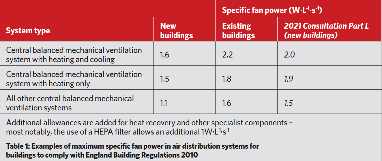
Table 1 provides an example of the requirements for centralised fan systems, taken from the guidance document5 for the regulations for non-domestic applications for England (the full document additionally includes values for other types of fan-powered ventilation systems).
The required values as shown in the table are significantly lower than those historically found in buildings.6 The recent 2021 consultation on potential revisions to Approved Document L Conservation of fuel and power provided a new set of target SFP values (as abstracted in the final column of Table 1). The apparent increase in SFP is misleading, as it now includes the previously separate allowance for a heat-recovery device and associated filter, as heat recovery is now the standard requirement for ventilation systems.
The design (and installation) of the AHU components, ducting, dampers, diffusers, grilles and flexible connections can offer the most immediate opportunity to reduce the resistance to airflow (as discussed in the October 2011 CIBSE Journal CPD). However, without applying effective fan technology, efforts to reduce air power used in the system will be somewhat wasted. As reported by Eurovent,3 the EU Ecodesign legislation has led to myriad innovations in the manufacturing of ventilation components. Motor and fan efficiencies have increased significantly, highly efficient energy-recovery components in mechanical ventilation systems have been enforced by law, and characteristic dimensions of AHUs grew by around 30% to meet the restrictions on the energy consumption of fans.
Probably the most common type of fans used in building HVAC are centrifugal fans with double inlets, backward curved centrifugal fans either with a scroll housing or as plenum, or plug fans, as shown in Figure 3. The plug fan effectively flings air in all tangential directions from the rotor, and the kinetic energy is quickly converted to static pressure, making the outlet stream less susceptible to system effects, and air enters the outlets as a fully developed, streamlined flow (as shown in Figure 4). The outlets should be smooth to reduce pressure losses.
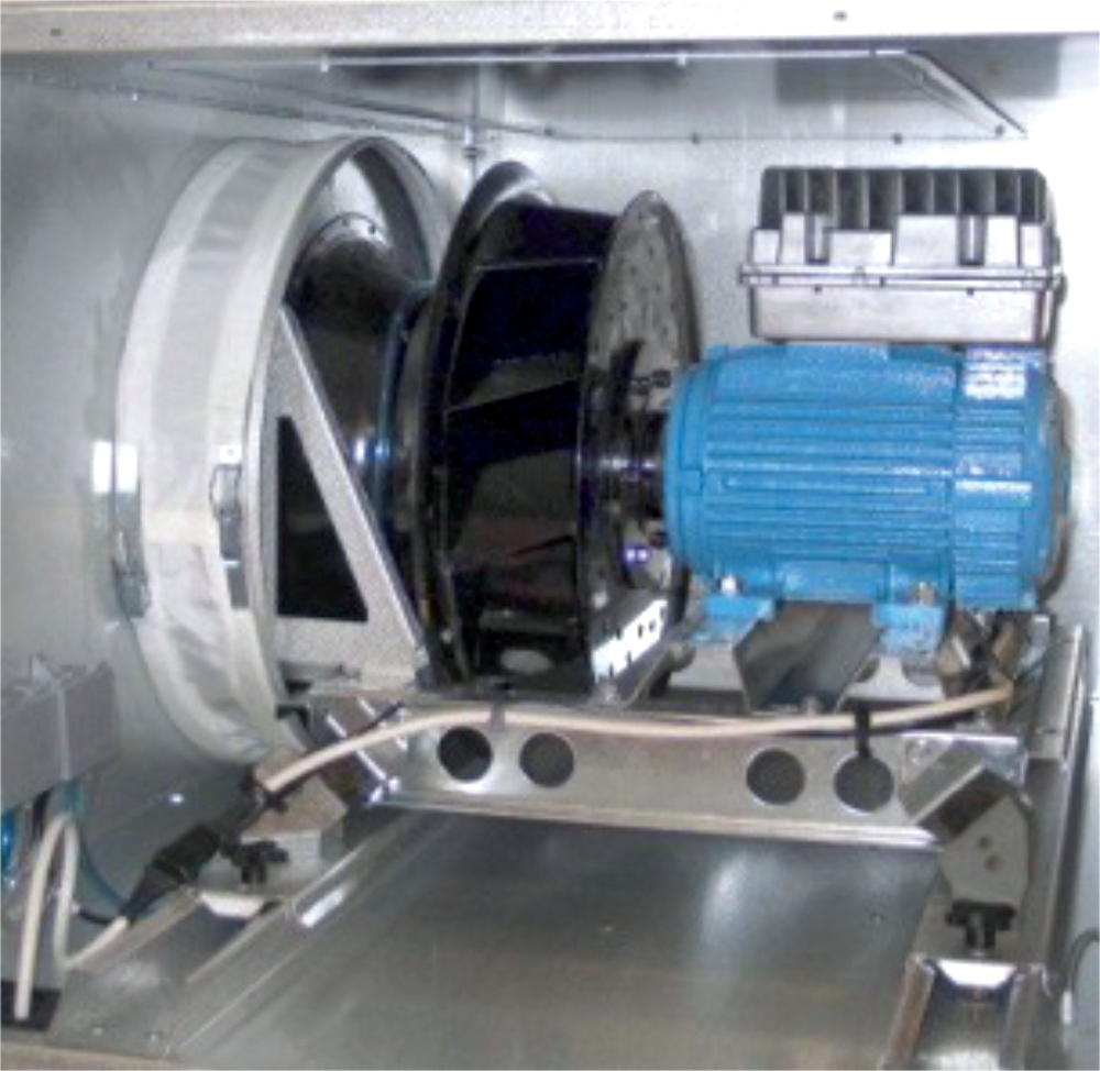
Figure 3: A plenum, or ‘plug’, backward-curved centrifugal fan
Although the smaller, forward-curved bladed centrifugal fan can deliver high airflows, it has lower impeller efficiencies, as well as high outlet velocities, and there is greater opportunity to suffer velocity pressure losses from system effects. Such fans are not typically applied in AHUs, as they would contribute to a high SFP.
When a fan is housed in an AHU or duct, there will be pressure losses and increased noise not accounted for in the standalone performance data supplied by the fan manufacturer. Some AHU manufacturers/integrators reportedly base their published fan performance data directly on information supplied by the fan manufacturer, although this would provide a misleading indication of performance.
As discussed by Berg,4 centrifugal fans with double intakes have been typically chosen for ventilation and air conditioning applications when relatively high outlet velocities are required – for example, more than 8m·s-1 – and the ducting is practically straight without any restrictions (caused, for example, by changes in cross-sectional area, sudden changes in direction, or by dampers or attenuators immediately on the output side of a fan). This would commonly be found in larger ventilation plants.
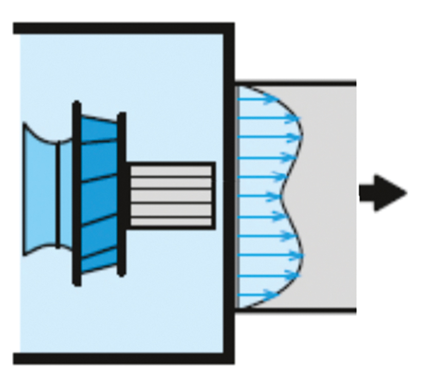
Figure 4: Velocity outlet profile from the plenum of a plug fan. The profile is fully developed and allows transitions close to the outlet of the fan (Source: Swegon)
Plug fans, employing directly connected inverter or electro-commutated (EC) drives, are typically used in smaller AHUs with lower airflows, and are commonly used for ductwork systems designed for lower velocities (for example, less than 6m·s-1), with consequently smaller pressure drops. They provide great flexibility in outlet connections (from the plenum), and do not require an uninterrupted length of straight duct at the outlet. The efficiency will be dependent on the fan’s location within the plenum and the relationship of the fan to its outlet – the plenum being used to convert the kinetic energy in the air to deliver the static pressure. Because of their simplicity and high installed efficiency, plug fans are increasingly being developed and applied in larger systems.
In terms of whole-life cost (and total-life carbon emissions), there is a limit to how low the SFP can go before the capital cost of the equipment outweighs the operational savings in lower pressure drops – this is discussed at length in CIBSE TM30 Improve life-cycle performance of mechanical ventilation systems. (The spreadsheet included in TM30, although a little dated in its example data, provides an excellent basis for examining the whole-life costs of a system, and can be readily extended to provide an indication of relative operational carbon impact.)
The Building Regulations5 in the UK limit the installed power that may be consumed by fans in ventilation systems in terms of SFP. In these regulations, the value of the SFP for an air distribution system accounts for the combined sum of the design watts of the system supply and extract fans, including losses through switchgear and controls (such as inverters), divided by the design airflow rate through that system. (See panel, ‘Setting the standard for SFP’).
Any such standardised SFPs should not be seen as the ultimate target. Better standards are achievable through careful, but typically simple, design practices – such as including turning vanes in bends – that can generate significant benefits in lifetime operational energy consumption, costs and carbon emissions.
© Tim Dwyer, 2021.
Further reading:
CIBSE TM42: Fan Application Guide (2006) provides detailed information on the assessment and installation of HVAC fans.
AIVC Technical Note 65, Recommendations on specific fan power and fan system efficiency gives detailed commentary and analysis of this application of fans for HVAC.
Swegon Air Academy AIR Chapter 25 Fans and SFP by Gunnar Berg inspired and provided content for this CPD article.
References:
1 www.gov.uk/government/publications/building-energy-efficiency-survey-bees – accessed 13 May 2021.
2 Schild, PG et al, AIVC Technical Note 65, Recommendations on specific fan power and fan system efficiency, AIVC 2009.
3 Eurovent Guidebook – air handling units, Eurovent 2018.
4 Berg, G, AIR Chapter 25 Fans and SFP, Swegon Air Academy, 2014.
5 Non-domestic Building Services Compliance Guide: 2013 Edition, NBS 2014.
6 Specific fan power – a tool for better performance of air handling systems, Jorma Railio and Pekka Mäkinen, Clima 2007.