![]()
In 2019, the UK formally committed to becoming a net-zero contributor to global warming by 2050. Despite the recent dip in greenhouse gas emissions resulting from the effects of the Covid-19 pandemic, there is no expectation that this downturn will continue, so the need for change is becoming more urgent. In the longer term, there is hope – as discussed in the other CIBSE Journal CPD article this month – that the electricity supply grid will be decarbonised and that there will be increased opportunities for a near ‘zero-carbon’ hydrogen gas supply network. Dependent on the success of current trials, a UK hydrogen gas network would not be a reality for another 10 to 15 years. The UK’s Clean Growth Strategy (published in 2017) envisaged that by 2030 there would be a 20% reduction in emissions below 2016 levels.
The most recent data of annual 2019 UK emissions1 are estimated as 435.2 million tonnes of carbon dioxide equivalent (MtCO2e) – a figure that has already benefited from the demise of coal as a means of electricity generation (with just 2.1% of electricity derived from coal2 in 2019). The UK ‘carbon budgets’3 have set a legally binding maximum number of ‘carbon units’ that can be produced by the UK across a series of five-year periods. The carbon budget for the 2028–2032 period is 1,725MtCO2e and, based on the most recent records of emissions, will require a reduction of more than 25% in annual emissions within the next nine years. And, since that carbon budget target was set, the UK’s subsequent commitment to net zero by 2050 will mean that there is a need to reduce annual emissions by nearer 30%.
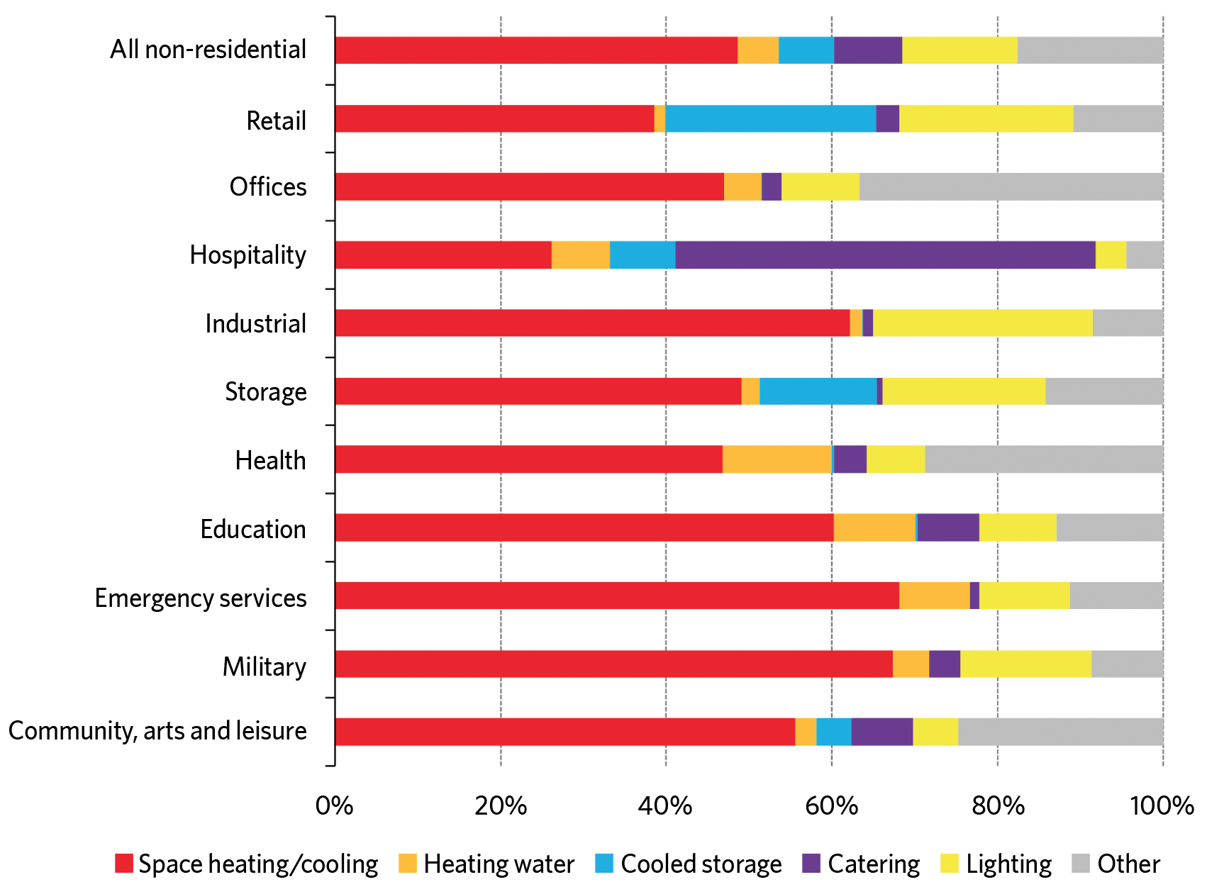
Figure 1: Examples of UK non-residential building energy consumption 2015-167
So, aside from the environmental imperative, there is a strong legislative incentive to decarbonise the energy supply networks, reduce the end users’ demand for heat, and increase the efficiency of heating appliances. Estimates of the UK non-residential demand for energy, as shown in Figure 1, indicate the significance of the energy used for heating/cooling (red) and hot water (orange). The heating demands are met predominantly by natural gas-fired water heaters.4 Emissions from UK fossil-based heating systems and stoves were 85MtCO2e in 2015, or 17% of the UK’s total emissions. Of this, non-residential buildings accounted for a quarter of direct emissions – 13MtCO2e from commercial buildings and 9MtCO2e from public buildings.5
The typical life of heating appliances in commercial buildings is in the order of 15 years, so any changes to reduce the environmental impact need implementing now. Otherwise, building operators could be left with ‘legacy’ systems for the life-cycle of the equipment or, worse still, possibly need to replace technically operational systems before the end of their economic life in order to meet more stringent environmental requirements. Alongside the drive to reduce carbon emissions, there are parallel demands to reduce the deleterious impacts on air quality from the local combustion of carboniferous fuels. This is reflected in several local development plans and notably in the London Environment Strategy6 that has set ambitious aims for ‘London to be a net-zero carbon city by 2030 and to have the best air quality of any major city’. It identifies air quality as the most pressing environmental threat to the future of health in London, highlighting particulates and nitrogen dioxide (NO2) – both produced from the combustion of carbon-based fuels. The policy explicitly supports the transition to low carbon – and low-pollution – heating alternatives such as heat pumps.
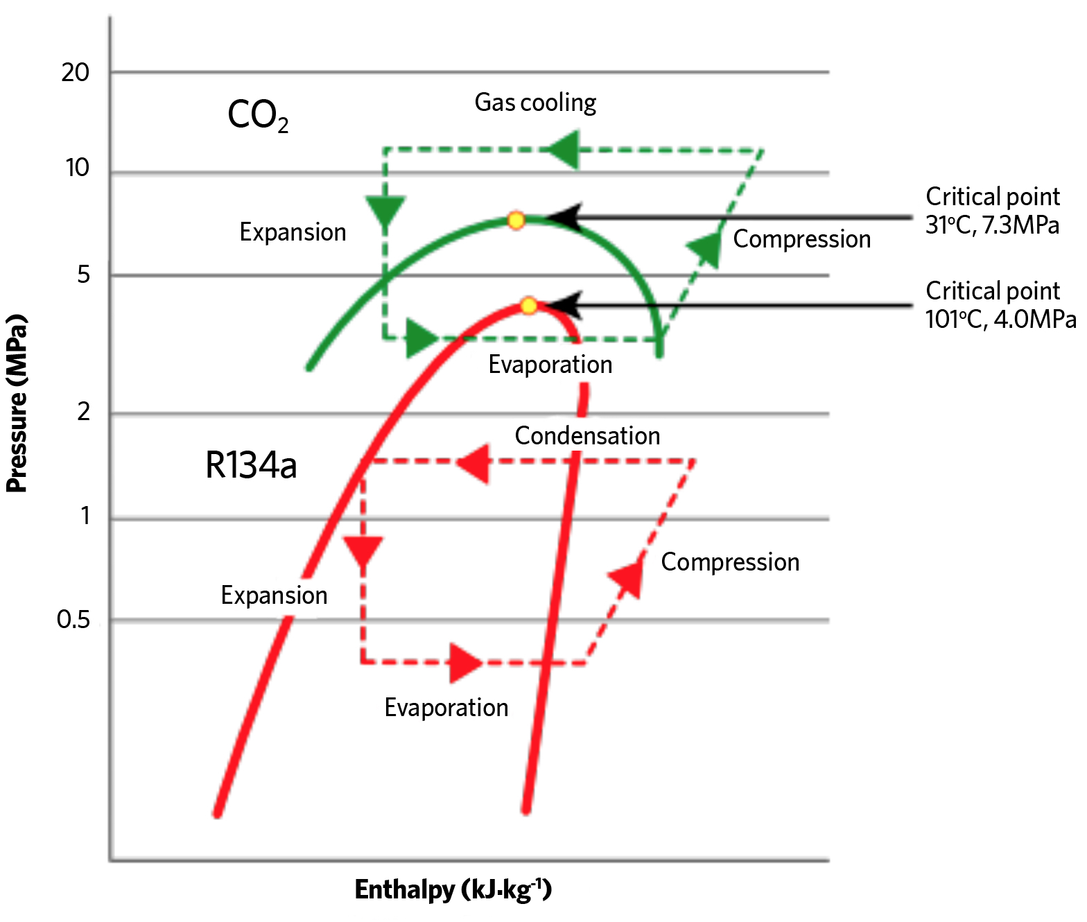
Figure 2: Simplified typical refrigeration cycles on P-h diagram for R134a and R744 (CO2)
So, there are good opportunities to investigate the use of alternative systems, and one of the most obvious is the new generation of heat pumps. The decarbonisation of the electricity supply grid in recent years has made a significant change when comparing natural gas fired water heaters with heat pumps as sources of building heat. The 2019 UK carbon factors8 for grid supplied electricity was 0.233kg.kWh-1 and for gas 0.184kg.kWh-1. If a direct-fired gas water heater is assumed as 98% efficient, then to obtain the same equivalent carbon emission per kWh of delivered heat in the commercial building would require a heat pump with a seasonal coefficient of performance (SCOP) of 0.233/(0.184/0.98) = 1.24. This is a relatively modest COP for a properly installed and operated heat pump. The expectation is that the carbon factor of grid electricity will continue to fall as the proportion of renewable sources are commissioned – for example, with the proposed increase in the fields of offshore wind turbines. This will further improve the relative carbon performance of heat pumps.
Typical commercial heat pumps are effective at providing low-temperature hot water suitable for space heating and, if installed and operated properly, are likely to provide season COPs of 3 and above. Current vapour compression heat pumps, though, have struggled to maintain good overall performance when producing significant amounts of domestic hot water at temperatures beyond 50°C. However, ‘transcritical’ carbon dioxide (CO2) refrigeration technology, as discussed in the 2012 CIBSE Journal CPD, Module 47, has now matured into commercial heat pump packages, so there are opportunities for efficient higher temperature operation.
CO2 is a naturally occurring substance that is non-toxic, non-flammable and environmentally friendly, with a global warming potential of 1 and ozone depletion potential of 0. CO2 also has a low critical point of only 31°C @ 7.3MPa, as shown in the pressure enthalpy diagram in Figure 2. At this critical point there is no separate liquid or vapour – it is a homogenous ‘supercritical’ fluid. When refrigeration cycles operate with heat rejection above this critical point they are said to be operating as a ‘transcritical’ system. This is where heat is rejected to the cooling water by de-superheating the CO2 vapour at a supercritical pressure in a gas cooler. As can be seen in the pressure-enthalpy diagram in Figure 2, the operating pressures for a CO2 system are many times that of a traditional vapour compression refrigeration system, such as the R134a cycle shown.
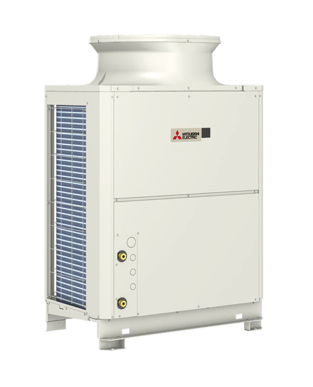
Figure 3: 40kW commercial air-sourced monobloc CO2 transcritical heat pump (1,837mm x 1,220mm x 760mm) (Source: Mitsubishi Electric)
The heat pump illustrated in Figure 3 is a 40kW commercial air-sourced monobloc CO2 heat pump designed specifically to supply domestic hot water between 55°C and 90°C. (‘Monobloc’ indicates that the heat pump unit and its refrigeration cycle is contained within one unit. No refrigerant flows outside of the monobloc casing – just water.) To provide high efficiencies, as well as to be able to work safely at the higher pressures required for CO2 transcritical operation, specifically designed components have been developed and optimised.
Referring to the schematic of a commercial monobloc transcritical air source heat pump in Figure 4, there are several technological aspects that allow safe, efficient operation:
The gas cooler, where the heat is passed from the refrigerant to the water, is an important element where effective heat transfer is critical to efficient system operation. So, for example, the system in Figure 4 employs a proprietary twisted and spiral gas cooler where three connected refrigerant pipes are wound around the twisted water pipe, as shown in Figure 5. The continuous spiral grooves in the twisted pipe increase the water turbulence (and so heat transfer) and also helps to reduce pressure losses within the heat exchanger, which contribute to enhance efficiency.
The compressor in this CO2 system appears externally similar to other scroll compressors. However, the internal components have been designed to operate effectively across a much greater pressure lift, and the shell thickness is approximately twice as thick as those used in a standard vapour compression system to withstand the higher refrigerant operating pressure. The integral drive motor has inverter speed control.
The flash Injection circuit (shown in orange in Figure 2) connects into a third injection port on the compressor to improve compressor performance during periods of lower ambient temperatures at the inlet to the air-side heat exchanger. This provides more stable water leaving temperatures at the lower ambient temperatures, while maintaining safe compressor operating temperatures and efficient operation.
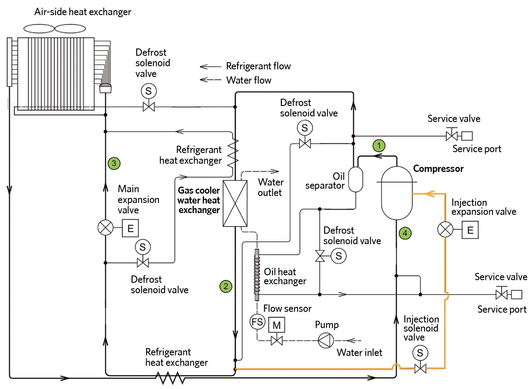
Figure 4: Simplified schematic of example commercial monobloc transcritical
air source heat pump for ‘high’ temperature water heating (Source: based on Mitsubishi Electric schematic)
In a standard cycle for this system, the CO2 leaves the compressor, point 1, between 100°C to 110°C and at a pressure of approximately 10MPa. The high-pressure, high-temperature gas flows into the gas cooler where the refrigerant exchanges heat with incoming cold water and de-superheats the CO2 gas by approximately 50K to 60K so the refrigerant gas temperature at point 2 is 40°C to 50°C. The CO2 passes through a refrigerant heat exchanger to superheat the incoming refrigerant before it flows into the expansion valve, where the CO2 pressure reduces to approximately 4MPa at point 3. The refrigerant passes through the evaporator and then back into the refrigerant heat exchanger, where it is superheated before entering into the compressor a point 4.
This particular unit is capable of water flow temperatures from 55°C to 90°C, and the unit works most efficiently when the return water temperature is 7°C to 15°C. If the water inlet to the gas cooler increases in temperature, the ability to de-superheat the refrigerant is reduced, as is the capacity and the COP. This may be acceptable in the later stages of heating a hot water storage tank but is not desirable for continuous operation. Such systems can be controlled in a number of ways, depending on the type of load. For example, hot water storage vessels can be maintained at 60°C to deliver a direct hot water supply or they can be heated to a higher temperature (up to 90°C), with plate heat exchangers employed on a primary circuit to heat secondary hot water supplies. This latter solution has the advantage that there is no storage of wholesome domestic hot water, so reducing opportunity for legionella bacteria growth.
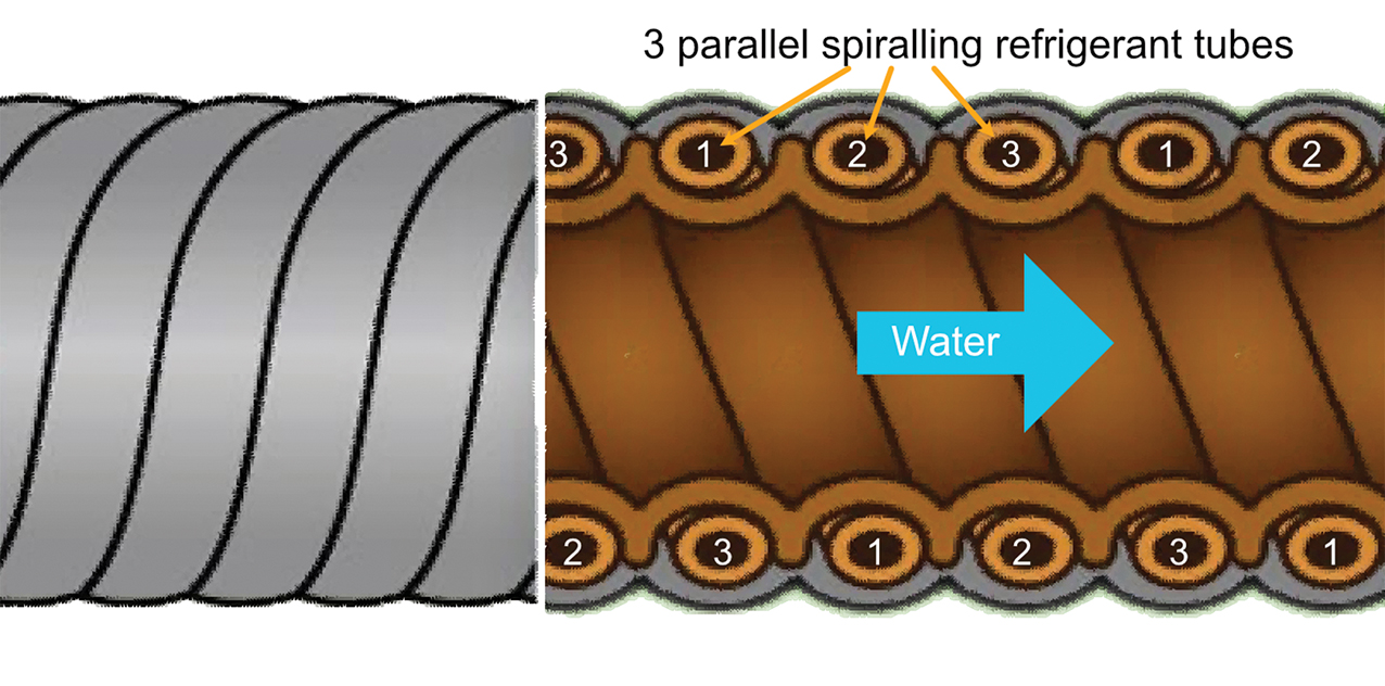
Figure 5: Simplified sketch of proprietary refrigerant gas-water heat exchanger
Seasonal efficiencies of the illustrated heat pump have been measured and tested for ErP lot 2 compliance, and shown to have a water heating efficiency (ηwh) of 171.9% for the average climate – an equivalent seasonal COP (SCOPDHW) of 4.29. A similar output modern gas boiler (used as part of an indirect hot water system) is likely to have a seasonal efficiency of approximately 0.90. In carbon emission terms, the basic heat generation emissions would be (0.233/4.29) = 0.054kg.kWh-1 for the heat pump and (0.184/0.9) = 0.20kg.kWh-1 for the natural gas system.
As noted in the 2018 study for the Greater London Authority,9 it is very difficult to draw a simple conclusion on capital costs, but ‘on average, the capital costs of heat pumps are likely to be slightly higher than a “business as usual” heating system’. The relatively small additional capital costs should be seen in conjunction with the potential benefits, including the reduction in carbon emissions and the much-reduced impact on air quality. The way that fuel is used to create heat needs to change rapidly if the government’s goals are to be met, and this may require some further incentives to soften the impact of the additional capital costs so that systems that are installed today do not thwart ambitions for a net-zero future.
© Tim Dwyer, 2020.
References:
- 2019 UK Provisional Greenhouse Gas Emissions – accessed 6 October 2020.
- UK Energy Statistics, 2019 & Q4 2019, UK Department for Business, Energy and Industrial Strategy, 2020.
- The Carbon Budget Order 2016 – accessed 6 October 2020.
- Next Steps for UK Heat Policy – Annexe 2, UK Committee on Climate Change 2016.
- Next Steps for UK Heat Policy, UK Committee on Climate Change 2016.
- London Environment Strategy, Greater London Authority, 2018.
- UK Building Energy Efficiency Survey 2014-15, BEIS 2016, www.gov.uk
- Greenhouse gas reporting: conversion factors 2020 – accessed 6 October 2020.
- Towards low carbon heat – Heat pumps in London, Etude, 2018.