![]()
The compressor serves as the core for the refrigeration cycle by receiving the low-temperature, low-pressure refrigerant vapour from the evaporator and conveying the high-temperature, high-pressure vapour onward, towards the condenser.
Refrigerant compressors that have evolved to serve unitary air conditioning units (or ‘room units’) have typically been positive-displacement compressors.
Examples of displacement compressors are reciprocating (piston) compressors, scroll compressors and rotary compressors, including screw and vane compressors, such as the rolling-piston rotary compressor.
The single-vane rotary refrigerant compressor, also known as a ‘rolling-piston’ type compressor – and often referred to simply as a ‘rotary compressor’ – has seen significant development over the past 40 years.
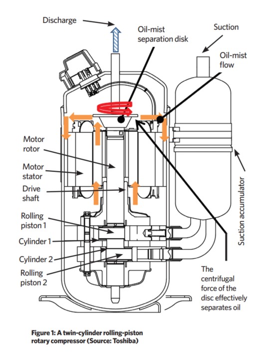
It comprises a drive motor mounted in line with, and above, the compression mechanism, which are both housed in the same shell (as shown in the diagram of a contemporary twin-cylinder rolling-piston rotary compressor in Figure 1). The shell provides a plenum for the high-pressure gas as it leaves the compression process.
The centreline of the drive shaft is the same as that of the cylinder in which it rotates. The shaft drives an eccentric cam inside the ring that drives the piston, so that as the piston revolves (or ‘rolls’ around the cylinder wall – as illustrated in Figure 2) it practically makes contact with the cylinder separated by an extremely thin film of specialist lubricating oil that acts to make a gas-tight seal between the piston and the wall of the cylinder.
There is a spring-loaded divider (the ‘vane’, typically manufactured in coated, high-speed steel) that is held in a slot-shaped chamber in the cylinder block that reciprocates (as it follows the eccentrically revolving piston).
This acts to separate the suction and discharge sides of the cylinder by maintaining a seal with the surface of the piston – again, with the high-viscosity lubricating oil to ensure an appropriate seal – with the two metal surfaces never actually meeting.
The spring and outermost section of the vane is at the same pressure as the shell – so, effectively, at the discharge pressure. This acts to hold the vane onto the piston, overtaking the work of the spring (that is primarily there for start-up purposes).
For the vane and the piston to maintain virtually perfect seals between the suction and discharge pressures, the ASHRAE Systems and Equipment Handbook1 notes that a ‘close tolerance and low-surface-finish machining is necessary to support hydrodynamic sealing and to reduce gas leakage’.
The lubricating oil is held within the high-pressure outer shell, so providing sufficient pressure to move the oil to the working surfaces to reduce frictional losses and ensure seals at the sliding vane and the interface of the piston and the cylinder.
For every two rotations, the compressor moves a volume of refrigerant from suction pressure to a higher pressure, into the discharge line. The suction is created by the increasing volume (on the low pressure side of the vane) as the piston rolls as shown in A -> B in Figure 2, so drawing the cool refrigerant gas into the cylinder.
As the piston revolves, the low-temperature, low-pressure gas is compressed in the cylinder until it becomes high-temperature, high-pressure gas, as shown in B -> C in Figure 2. When the gas pressure in the cylinder rises above the high pressure inside the shell, the discharge valve opens (that is likely to be a simple reed valve) and the gas discharges, as shown in Figure 2 D.
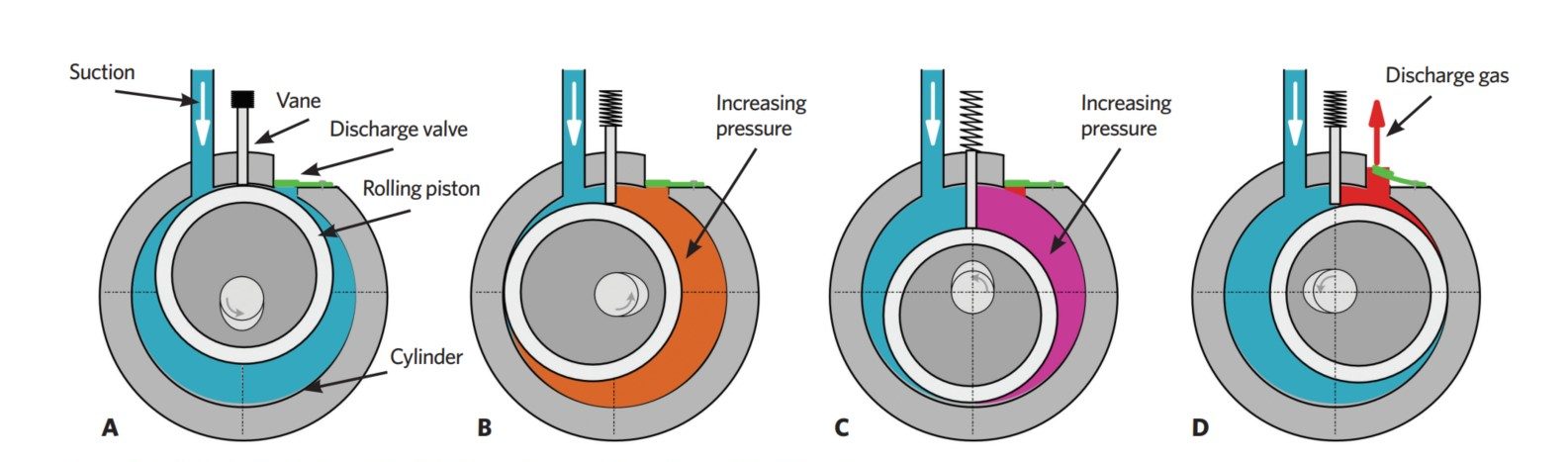
Figure 2: Simplified functional diagrams illustrating the 360° compression cycle of a rolling-piston rotary compressor
In the example compressor in Figure 1, the high-temperature, high-pressure gas discharged from the cylinder passes into the space in the upper section of the shell, through gaps between the motor and the shell, and then to the discharge pipe.
The rising gas will provide cooling for the motor windings, and the motor will also separate the oil from the refrigerant gas by the centrifugal force of the rotor. The example in Figure 1 also includes a specific rotating oil-mist separation disc to increase the oil separation.
A small amount of oil passes from the rotary compressor into the discharge pipe – a fraction of that in other types of positive displacement compressors. Any excess oil circulating with the refrigerant, as it passes through the distribution system, will reduce the performance of heat transfer surfaces.
Reducing the entrained oil is particularly beneficial when rolling-piston compressors are part of a system that supplies the lengthy piping of variable refrigerant flow (VRF) and other similarly extensive systems.
Interest accelerated in optimising the operating efficiency of rolling-piston compressors following the energy crisis of the 1970s, and was discussed in a paper by Matsuzaka2 nearly 40 years ago.
On investigating the performance of the hermetic rolling-piston rotary compressors of the time (and as confirmed latterly by ASHRAE1), he determined that the relatively small clearance volume (the volume of high-pressure gas that remains in the cylinder when the discharge valve closes) leads to very little re-expansion, and so the ‘volumetric efficiency’– the ratio of the amount of refrigerant gas entering the compressor to the amount of gas leaving it – is very high.
As designs have evolved in the intervening years, the discharge port has been optimised to both reduce frictional losses and further minimise the amount of residual gas.
In addition to high volumetric efficiency, rolling-piston technology has a resilience against ‘slugging’ (liquid refrigerant entering through the suction line).
As a further safeguard against slugging, a suction accumulator (as shown attached to the compressor housing in Figure 1) provides a trapping device to ensure any returning refrigerant that is in a liquid state is vaporised before entering the compressor (together with entrained, returning oil).
As discussed by ASHRAE,1 the mounting of the motor stator (fixed in the upper part of the housing), as well as the rotors, can cause significant torsional vibration that, unless properly minimised or compensated with appropriate resilient components, can transmit noise and vibration beyond the compressor housing. (There is, however, likely to be significantly less vibration compared with reciprocating compressors, as there is no conversion from rotation to reciprocation.)
Although the motor provides a constant force, the compression process needs a varying force, as the compression rotation torque required just before discharge (Figure 2 C and D) is larger than that required at the start of compression (Figure 2 A). This difference between the force generated by the motor (the motor torque) and the compression torque required for compression will cause vibration.
To reduce this issue, twin rotary compressors were developed that included two pistons, each in a separate cylinder, one above the other on the same drive shaft but rotationally positioned 180° apart. Not only does this reduce vibration by having the balancing forces of the two pistons, but it also makes it possible to design larger capacity rotary-piston compressors.
The advent of low-cost inverter-controlled motors has enabled operation at a wide range of speeds for the twin-rotary compressor. Being able to modulate output means that the compressor is better able to match the requirements of the load.
For example, operating the compressor at low output provides a far more satisfactory system response compared with frequently cycling the compressor on and off.
However, at low outputs, the frictional losses at the interface between the vane and the piston have a greater impact on the operational efficiency. In their drive to improve operational efficiency, compressor manufacturers are continuing to pursue technical developments to reduce such friction losses.
One of the technologies designed to improve operational efficiency at low outputs was reported by Hirano et al3, and a mechanism was subsequently developed over the past 10 years, as shown in the illustration of a simplified system in Figure 3.
In normal two-cylinder operation, the lower compressor vane is pushed against the rolling-piston by the force generated by the pressure difference between suction pressure at the vane tip and the discharge pressure in a separated vane chamber acting at the back side of the vane (as in Figure 3 A) – note that in this system the second compressor vane does not have a spring.
In this operating mode, the three-port valve is set in the normal operating position. When the refrigeration load does not demand the need for a second compressor, it is set to idle running by setting the three-port switching valve, as shown in Figure 3 B.
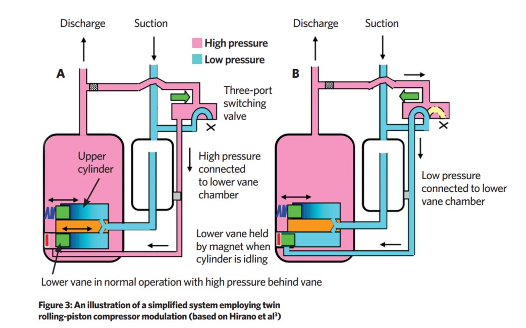
In this position, the pressure in the separate chamber behind the vane of the lower cylinder will be maintained at low (suction) pressure, and so the vane is not pressed against the piston and a permanent magnet holds the vane back into the housing.
The piston will, of course, continue to rotate but will not suffer from the same frictional loss. When two-cylinder operation is required, the three-port switching valve reverts to its normal position.
This arrangement provides an operating range to efficiently deliver between approximately 10% and 100% full load. This technology is capable of delivering high-efficiency operation. However, to date, it has only been applied in a limited number of high-end products.
The opportunities afforded by wider operating ranges have encouraged the development of larger rolling-piston compressors that, as they become larger, provide further challenges to maintain efficient and low-vibration operation.
The use of electronic motor control, primarily used to vary the compressor speed, has enabled the development of advanced torque control, so that the provided motor torque can be automatically adjusted to deliver the force required by the compressor and reduce risks of vibration.
There are increased thrust forces on the vane as the cylinder increases in height (in larger compressors), so causing increased friction where the vane meets the piston. To overcome this, the vane has effectively been split in the axial direction to make a dual vane for each cylinder, with each one subject to a dispersed and reduced thrust force, so reducing the losses – and the potential wear – in the vane.
In the past, nitriding was mainly used for surface treatment of vanes. Recently, diamond-like carbon (DLC) has been put into practical use to make vanes resistant to a higher temperature and a higher load, enabling a higher sliding speed. DLC has a coefficient of friction about two-thirds that of conventional materials, and so reduces the sliding loss of vanes.
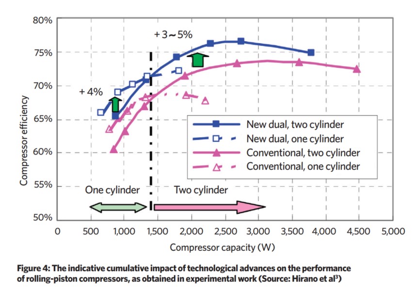
The advances in rolling-piston compressors – including the adoption of two cylinders, enhanced digital motor control, new technology surface coatings and improved fabrication techniques – have combined to both improve the efficiency of the compressors and extend their operational range, as illustrated in the experimental data from Hirano4 in Figure 4.
As the technology of rolling-piston rotary compressors continues to develop, they can provide a good solution for small air conditioning units.
At the same time, they are also increasingly being applied to applications in large chillers where multiple rolling-piston rotary compressors can provide efficient modular, parallel compression for large centralised cooling and air conditioning applications.
© Tim Dwyer, 2020.
References:
1
2016 ASHRAE Handbook – HVAC systems and equipment, Chapter 28 section 3.
2
Matsuzaka, T el al, Rolling-piston type rotary compressor performance analysis, International Compressor Engineering Conference, School of Mechanical Engineering, Purdue University, 1982.
3
Hirano, K et al, Development of a new mechanism for dual rotary compressor, International Compressor Engineering Conference, School of Mechanical Engineering, Purdue University, 2012.
4
Hirano, K et al, Development of a high-efficiency dual rotary compressor for air conditioner, International Compressor Engineering Conference, School of Mechanical Engineering, Purdue University, 2010.