![]()
Heat networks serve nearly half a million consumers across 17,000 heat networks in the UK. Some 90% of the connections1 are to domestic customers, with the remainder spread across commercial, retail, industrial and institutional users. Networks vary in size and length, from those carrying heat just a few hundred metres between homes and flats, to systems of several kilometres supplying entire communities and industrial areas.2 Heat networks currently provide around 2%3 of the overall UK heat demand, but government research suggests that 14-20% of the UK heat demand could be cost-effectively met by heat networks by 2030, and 43% by 2050. It is, however, estimated that around 18% of UK heat will need to come from heat networks by 2050 if the UK is to meet its carbon targets cost effectively. These factors – combined with the growing interest and adoption of ambient temperature loop systems that integrate heat pumps into district schemes – are driving forward the development of new networks.
The water circulating in a district energy system will inevitably be treated in some form, but work recently published by Greaves4 illustrated that 15% of the 185 UK heat networks studied had suffered failures as a result of issues around water quality. Heat exchangers transfer the heat from the primary water flowing around the network to the local loads, and many hundreds of thousands of these will be stand-alone brazed plate heat exchangers (BPHEs), which are also employed in heat interface units (HIUs), such as that shown in Figure 1.
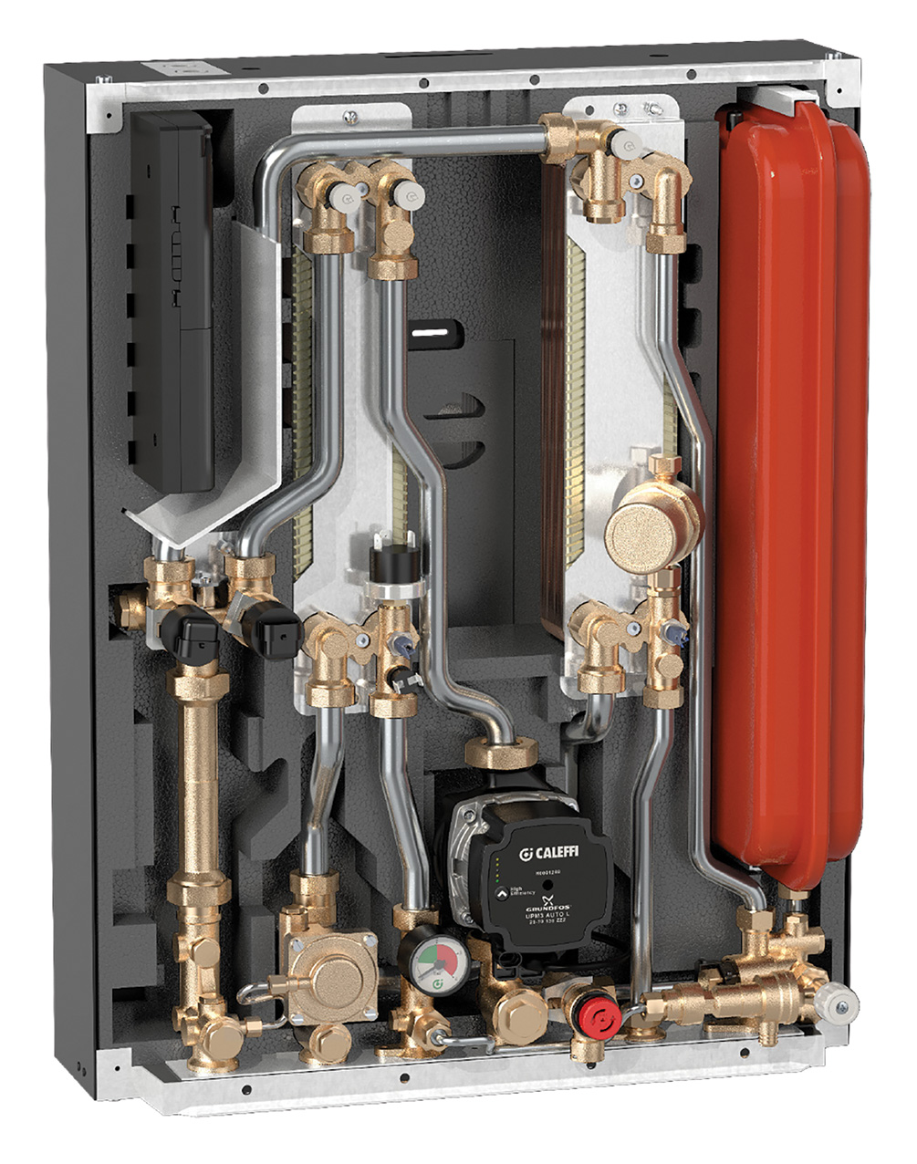
Figure 1: Example of heat interface unit (Source: Altecnic)
BPHEs such those employed in HIUs, and larger system BPHEs such as shown in Figure 2, are normally manufactured from pressed stainless steel plates, the plate being embossed with an optimised variant of a ‘herringbone’ type pattern. These are sandwiched with a copper foil, and pressed and brazed together – typically with copper – to form a compact and effective heat transfer device.
The effectiveness of the heat exchanger is dependent on the thickness and conductivity of the stainless steel plates that divide the two flowing fluids; the surface heat transfer coefficient on both sides of the plates; and any thermal resistance because of ‘fouling’. The thin – approximately 0.4mm – stainless steel plates have a very low thermal resistance and, because of the turbulent flow through the heat exchanger, there is very little deposition and accumulation of unwanted materials on the surfaces – therefore, fouling factors are typically low. The surface heat transfers are dependent on the fluid characteristics and the flow, and so are set by the application. (See CIBSE Journal CPD module 118, November 2017, for more details of BPHEs.)
When the BPHE is used in an appropriately controlled environment, there should be no corrosion problems, since neither stainless steel nor copper corrodes easily. However, high chloride levels in an oxidising environment can initiate the corrosion of stainless steel, particularly at higher water temperatures, as the chlorides form a galvanic cell with oxygen and the metals of the BPHE. Chlorides are widely distributed in nature as salts, such as sodium chloride (NaCl), potassium chloride (KCl) and calcium chloride (CaCl2). The most common form of resulting damage is pitting corrosion, with the chloride attacking areas of the steel where the passive layer is damaged (the passive layer is the protective surface film that is formed when stainless steel is exposed to air).
Coating stainless steel for enduring performance
Examples of coated stainless steel plates (Source: Swep)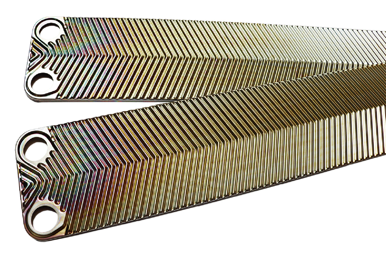
Pitting corrosion is hard to detect and might only be identified when a unit has started to leak. Another common – and very similar – type of corrosion for stainless steel is crevice corrosion, which can occur at, or immediately adjacent to, a gap or crevice between two joining surfaces. The gap or crevice can be formed between two metals or a metal and non-metallic material, and may occur in welds that fail to penetrate, in flange joints and under deposits on the steel surface where the passive layer has failed to form. Outside the gap or without the gap, both metals may be resistant to corrosion.5 Higher temperatures make chlorides more aggressive towards stainless steel. The grade of stainless steel used in the systems should account for the temperature and chloride concentrations – manufacturers will be able to provide advice.
The majority of BPHEs use copper as the brazing material, which has good resistance to corrosion in the majority of likely water qualities. If the water has a low pH (more acidic), the copper can start to corrode or dissolve in the water. Copper is also very sensitive to ammonia and sulphur. Ammonia has been used in some district energy systems to regulate the pH, so if copper is used as the brazing material, it is recommended that the ammonia level be kept very low. (A normally preferred alternative chemical to regulate pH is, for example, sodium hydroxide.) BPHEs are available that employ a nickel alloy as the brazing material (instead of copper) – resistant to both high sulphur and ammonia contents.
Both copper and stainless steel are susceptible to corrosion in strongly acidic solutions, but copper is the more vulnerable metal in an alkaline environment.
Copper may also be compromised by the presence of dissolved salts, but maintaining electrical conductivity of the water within the recommended range will minimise this source of corrosion. Conductivity measures the ability of a solution to carry an electric current because of the presence of certain ions, and is usually expressed in micro siemens per centimetre (μS.cm-1). Conductivity is also affected by temperature – the warmer the water, the higher the conductivity – and so is normally reported as conductivity at 25°C. The concentration of total dissolved solids in milligrams per litre (mg.L-1) can also be calculated by multiplying the conductivity result by a factor.
Oxygen content
The presence of oxygen increases the risk of corrosion, so the oxygen content should be kept as low as possible. When adding make-up water, it is important to ensure that either the water has been de-oxygenated or that appropriate additives have been used.
The typical recommendations are that the water circulating in the network should have an oxygen content less than 0.02mg.L-1, be a weakly alkaline environment with a pH preferably between 7.5 and 9, and should contain the lowest possible presence of ammonia and sulphide.
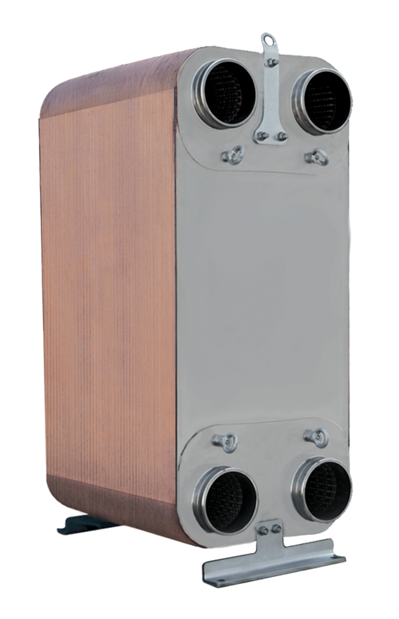
Figure 2: A BPHE developed for heat network applications that can typically deliver up to 10MW heat transfer
Fouling is the term used to describe the tendency of a fluid to form a film or scale on the heat transfer surface, and is an undesirable phenomenon. Inorganic materials may crystallise as salts, resulting in scaling. Organic deposits include biofilms or microbial organisms. If inorganic or organic material starts to build up inside the BPHE, it will result in lower heat transfer and a higher pressure drop.
Scaling is a type of fouling caused by inorganic salts in the water passing through the BPHE, which may precipitate and form a scale on the heat transfer surface. Most scaling is the result of either calcium carbonate (CaCO3) or calcium sulphate (CaSO4) precipitation. It increases the pressure drop and insulates the heat transfer surface, thus preventing efficient heat transfer. Scaling is more likely to occur when the fluid velocity is low (laminar flow) and the liquid is distributed unevenly through the passages on the heat transfer surface.
The solubility of salts in water decreases with increasing temperature, so the salts are, therefore, deposited on the warm surface when the cold water makes contact with it. Scaling is more likely at a high pH, and the risk of scaling generally increases with increasing water temperature. Experience shows that scale is seldom found where wall temperatures are below 65°C. To reduce the risk of scaling, the highest possible water pressure drop across the heat exchanger should be employed.
A high pressure drop implies turbulence and higher shear stresses. The shear stresses work as descalers by constantly applying forces to the adhered material that pull the particulate material away from the surface, as shown in Figure 3. For a BPHE with a temperature above 70°C on the hot side and/or very hard water (and a high risk of scaling), the pressure drop should be increased as much as possible on the cold water side.
Particulate fouling
Particulate fouling is caused by suspended solids such as mud, silt, sand or other particles in the water systems. Particulate fouling can influence the performance of the heat exchanger, depending on the particle size. If the particles are large (>1mm) or have a fibrous structure, they may lodge in the inlet of the heat exchanger or clog the channels. The result is an increased pressure drop in the water circuit of the heat exchanger. Clogged channels also mean low water velocities and so reduced heat transfer. Particles may adhere to the heat transfer surface and build up a layer of low thermal conductivity material.

Figure 3: An illustration of how the turbulent flow and shear stresses help keep the BPHE clean
Initially, this leads to reduced heat transfer, and subsequently a higher pressure drop in severe cases of fouling. Turbulent flow will keep particles in the fluid in suspension, which will help avoid surface fouling, with the scouring action cleaning the heat transfer surface. As the fluid passes through the channels, it constantly changes its direction and velocity. This ensures turbulent flow even at very low flowrates and pressure drops. The flow depends on the design of the plate pattern but should be evenly distributed across the heat transfer surfaces to maintain uniform velocity. The normal practice is to have the cold water entering the lower port whenever possible, because if it enters through the upper port, it may encourage debris to enter the channels. The distribution pattern in the port areas of well-designed BPHEs ensures a well-distributed flow.
Rough surfaces will encourage fouling by collecting particulate matter. The stainless steel plates provide a smooth surface that minimises fouling, and manufacturers are introducing novel surface coatings to further enhance this (see panel). Manufacturers must carefully organise brazing points (during manufacture) to reduce the opportunity for pockets of stagnant water.
If bacteria enter the heat networks, their small size (around 1μm) enables them to penetrate throughout the system – bacteria can live with or without oxygen.
Organic deposits/biofilms can reduce the heat transfer in the BPHE, and can also block the flow channels. The deposits can result in microbial corrosion and may require specialist biocide treatment. Appropriate chemical treatment of water can also control suspended particulates.
The channels in a BPHE may clog if particulate matter is not prevented from entering the unit, which then also increases the pressure drop. The piping system must be properly flushed before the BPHE is connected to ensure the removal of material that could cause fouling or clogging. To reduce the risk of a particulate sludge forming inside the BPHE, a filter or appropriately meshed strainer should be installed. Sidestream filters are also frequently employed that – as the name suggests – are connected in a bypass arrangement to the main flow, to filter a percentage of the full flow so that the complete system volume is filtered two to three times every 24 hours. These are cost-effective and readily maintainable compared with installing a single large filtration system to handle the full flowrate. Fouling can be caused by corrosion, particularly from other parts of the system. These particles will be carried by the water and may adhere to the heat transfer surface or lodge inside the heat exchanger. For applications with a high concentration of magnetite in the water, such as those with a high leak rate, a filter with a magnetic function is typically recommended. Besides filters, air and dirt separators may be employed to minimise air and particulate matter, reducing maintenance needs and improving performance.
There are some recommended operating practices to ensure the continued effective operation of BPHEs as part a heat network (which have been abstracted from more extensive information in CP1: Heat Networks: Code of Practice for the UK6 and the recent CIBSE Journal article by Greaves4):
- There should be, as a minimum, continuous monitoring for pH and conductivity, with remote reporting and alerts
- Pressure differences should be monitored across strainers and sidestream filters
- Automatic chemical dosing based on continuous monitoring should control
• pH levels to a narrow tolerance
• excessive oxygen levels
• biofilms, especially when operating with flow or return temperatures below 60°C - Manual weekly checks should be undertaken to identify any water losses, and there should be a monthly analysis of water chemistry
- Any make-up water should be treated prior to adding to the system
- Water treatment, fill water quality and method and pressurisation should be considered at design stage, based on system volumes and metallurgy.
© Tim Dwyer, 2019.
Further reading:
A new edition of CIBSE/ADE CP1: Heat Networks: Code of Practice for the UK will be published early in 2020, and will include further detail of water treatment.
There is a very useful guide – Recommendations – Water Treatment and Corrosion by the Danish District Heating Association, with an English translation.
For underlying knowledge on water treatment in closed systems, a core reference is BSRIA BG50/2013 Water Treatment for Closed Heating and Cooling Systems.
References:
- Market Report: Heat Networks in the UK, ADE, January 2018.
- Heat networks, The Association for Decentralised Energy – accessed 10 December 2019.
- Ford, R, Government support for heat networks – an update, EcoBuild 2018.
- Greaves, J, The scale of the problem – water quality issues in heat networks, CIBSE Journal, July 2019.
- Different types of corrosion, WebCorr Corrosion Consulting Services – accessed 10 December 2019.
- CP1: Heat Networks: Code of Practice for the UK, CIBSE/ADE 2015.