![]()
UK water authorities are obliged1 to supply water at a minimum 70kPa (0.7 bar) at the point where the communication pipe joins the consumer supply pipe, which equates to approximately 7m head (height) of water. This provides a minimum standard that could be sufficient to supply water to the top of a two-storey house, but in newer homes – especially those with unvented heating systems – all the hot and cold taps are likely to be supplied directly under mains pressure,2 and 70kPa may not be sufficient to serve showers on the first floor properly. There are good reasons for moderating mains pressures to reduce network costs and losses and, in many cases, sanitary fittings that have a high inlet water pressure can use excessive water (as discussed more fully in the Wrap publication Reducing water use – pressure, pipework and hoses). There are, however, many sanitary fittings (particularly showers and commercial equipment) that require water static pressure in excess of 1 bar to operate correctly.
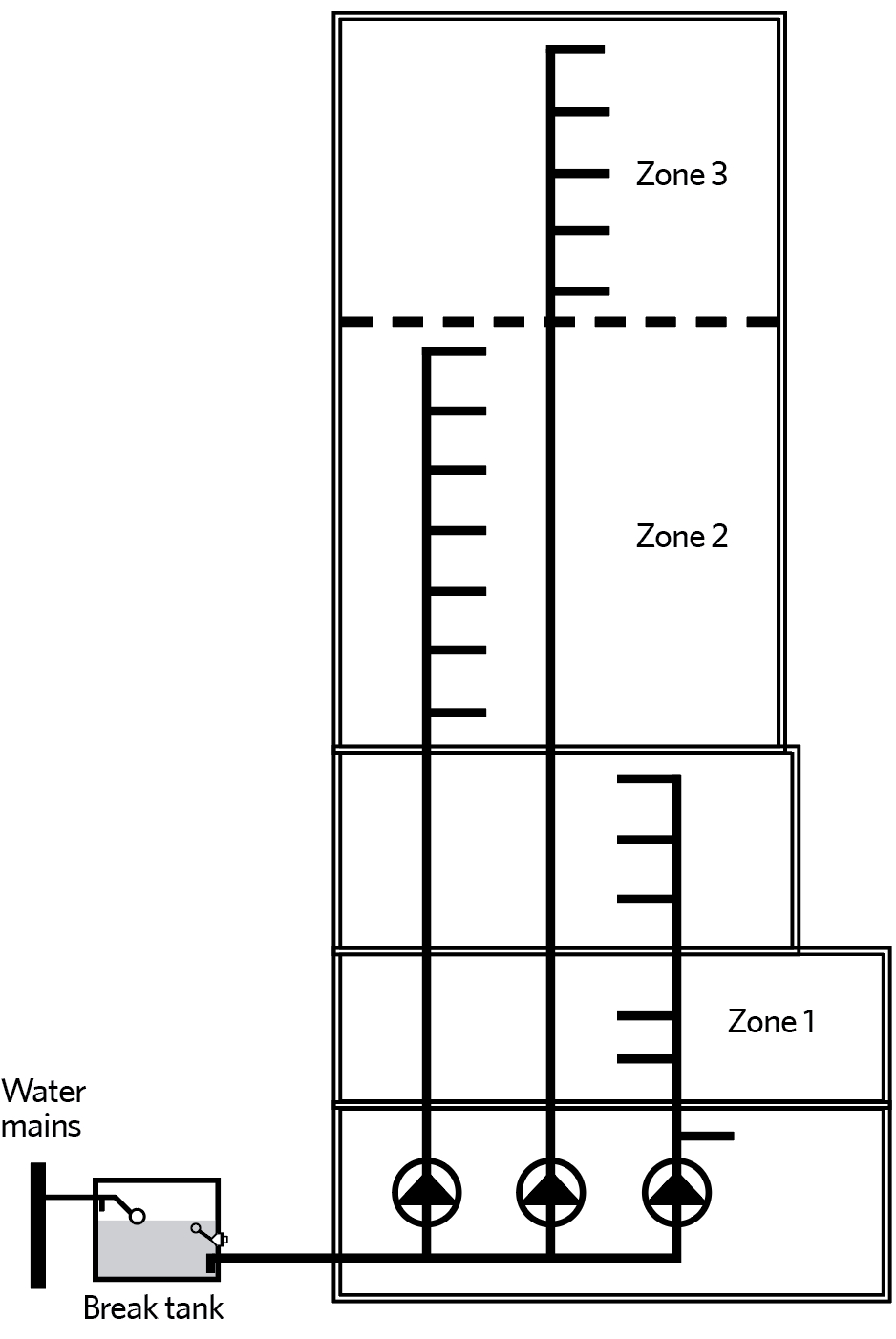
Figure 1: Pressure zoning in a high-rise building (Source: CIBSE Guide G)
For larger and taller installations, mains water pressure can be an issue, as it is unlikely to be able to deliver water beyond three to five storeys, and is then dependent on any subsequent changes in the water network, such as new local developments and the deterioration of supply pipes. If the supply pipework is undersized or installed based on the assumption of a higher mains pressure (that has subsequently dropped), the static pressure may fall below that required for adequate flow through the outlets.
The methods for assessing the required flow of water in building pipework systems are increasingly under review, with traditional estimating methods apparently leading to oversizing (as recently reported by CIBSE Journal in articles by David Glossop and Achala Wickramasinghe in the April 2019 issue). It is not an exact science, since it is dependent on the vagaries of the occupants’ water consumption. The designed water service must also comply with current UK building regulations, such as described in England Building Regulations AD G,3 that limit the designed daily water consumption ‘for the prevention of undue consumption of water’. Very few systems will be sized for all outlets to be supplied simultaneously. The CIPHE loading unit system,4 which accounts for diversity of use, currently ‘offers a recognised industry standard for the sizing of pipework systems within the UK’,5 and is the method that is adopted in chapter 2 of CIBSE Guide G.6
Whatever the flowrate that has been assessed, the regulations to ensure water quality require that the water supplied must be ‘wholesome’.3 The building’s water systems must also be designed to ensure that there cannot be any backflow from the building systems that could contaminate the water supplier’s main distribution network.
In smaller, typically domestic applications, a pump can be used as a direct booster by drawing water directly from the water mains at a maximum flowrate limited by the water suppliers, but must not allow backflow into the mains. However, in larger systems, the booster pump typically draws water indirectly from an intermediate – or ‘break’ – water store. Such stores will be referred to as ‘cisterns’ in this article, and may include one-piece cisterns, sectional tanks or any other vessel open to atmospheric pressure but sufficiently sealed to prevent airborne contamination. The stored water provides a physical break from the main supply, so preventing backflow while also maintaining water supply to outlets under peak flow demands, possibly when the supply from the mains supply is insufficient. Depending on application, this can provide storage sufficient for, typically, up to 24 hours’ consumption (as detailed in CIBSE Guide G section 2.3.2). As described by CIBSE Guide G, pumping will provide flexibility in the positioning of storage cisterns, as well as ensuring that there is sufficient remaining operating pressure at the outlets to deliver the required flow at times of peak simultaneous demand.
Water pressure
Common units: 1 bar = 100kPa ≈ 10m head.
Static head is because of the height difference, z (m), between the water source and the point of use. Static pressure = ρgz where ρ=density of water (≈ 1,000kg.m-3), g = acceleration as a result of gravity (9.81m.s-2).
Distribution dynamic pressure loss is because of flow losses through pipe length, valves and fittings, and is normally calculated for the index run of pipework.
Required ‘dynamic’ outlet pressure is typically between 0.2 and 4 bar, depending on the type of fitting.
Pump ‘booster’ sets may be used to move water from smaller low-level break cisterns to larger high-level cold-water storage cisterns, so that water can then be supplied using a gravity flow system. The pump set can move water to the higher-level cisterns (or multiple cisterns at intermediate levels serving groups of floors) at a rate that is significantly lower than the peak water usage, making use of the buffer provided by the distribution cisterns. This combination of pumped and gravity feeds would continue to provide water in the event of a failure of the pump. Depending on the application, such a system may also require pumping (from the high-level tank) to the final outlets on the top floors of the building in order to meet the pressure requirements of fittings that cannot be fully met by the available static head.
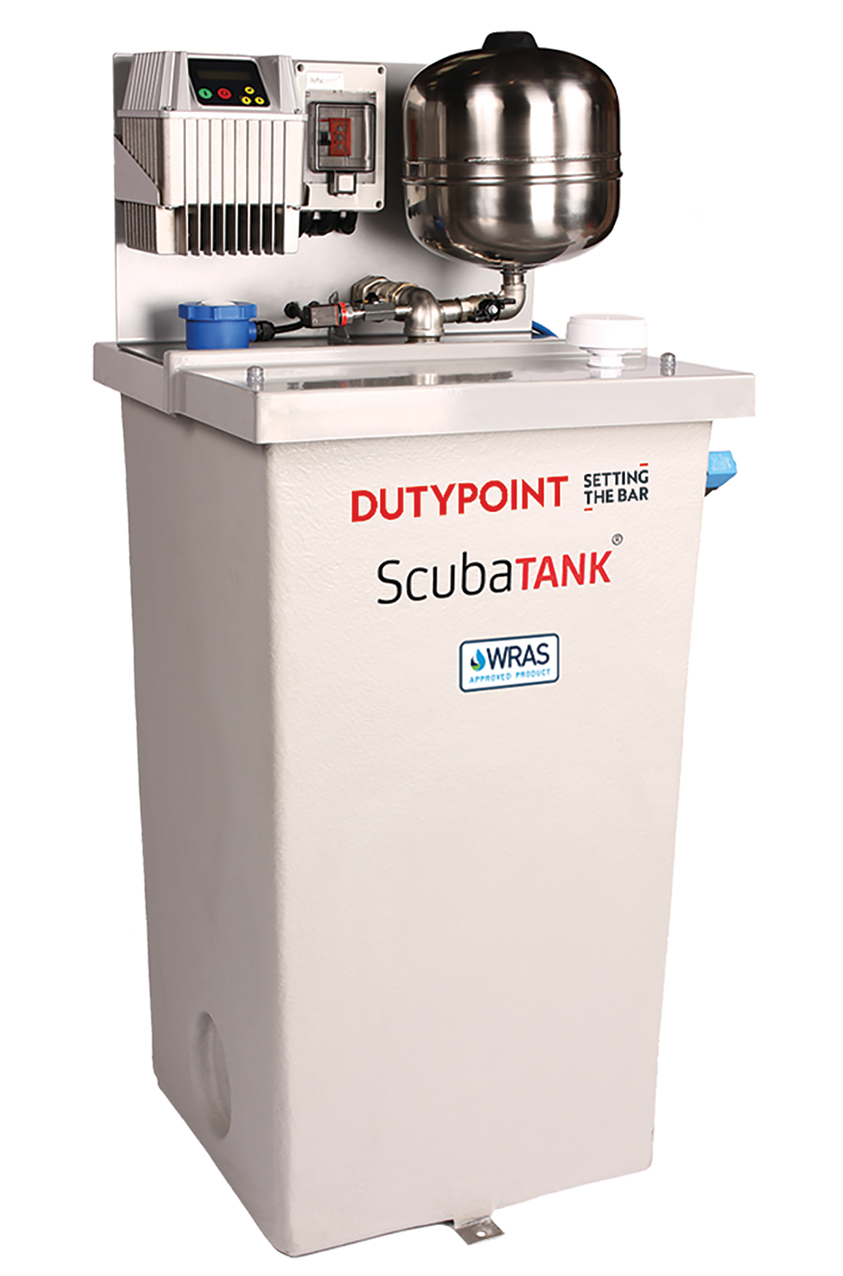
Figure 2: Example of an all-in-one tank and booster set
Booster sets may also be used to pressurise both the hot- and cold-water systems directly, drawing from a break cistern without any further storage, as in the example shown in Figure 1. This is the most popular arrangement6 for contemporary UK commercial multi-storey buildings and reduces the risk of contamination by removing the need for distributed storage cisterns.
Where this is used in high-rise commercial developments, the pressure delivered (see ‘Water pressure’ panel) will typically be zoned with a separate pump set and riser pipe for each pressure zone, as in the high-rise building illustrated in Figure 1. This reduces the risk of developing excessively high pump pressure within system pipework and fittings in the lower levels of the building. CIBSE Guide G provides guidance for the appropriate delivery pressure to the initial floor in a group ranging from 800kPa for groups of six floors up to 1,000kPa for a 12-floor group. There may be a need for pressure-reducing valves on the lower floors of the groups to moderate the pressure for some fittings.
For low-rise buildings – such as small apartment blocks (up to six floors) – and light commercial applications, a simple variable speed pump set can be used, such as that shown in Figure 2. The pump normally has a flooded suction (that is, the inlet is below the water level in the break cistern), and delivers water to each tap and outlet to meet demand.
For applications such as single dwellings, an automatic pressurised pumping system supplying water direct from the water supply to all taps and outlets can be used but must be carefully selected and operated, otherwise it might cause significant issues in the systems. The UK water regulations allows up to 12 litres per minute to be drawn from the water main by such an arrangement without the requirement for water authority consultation.
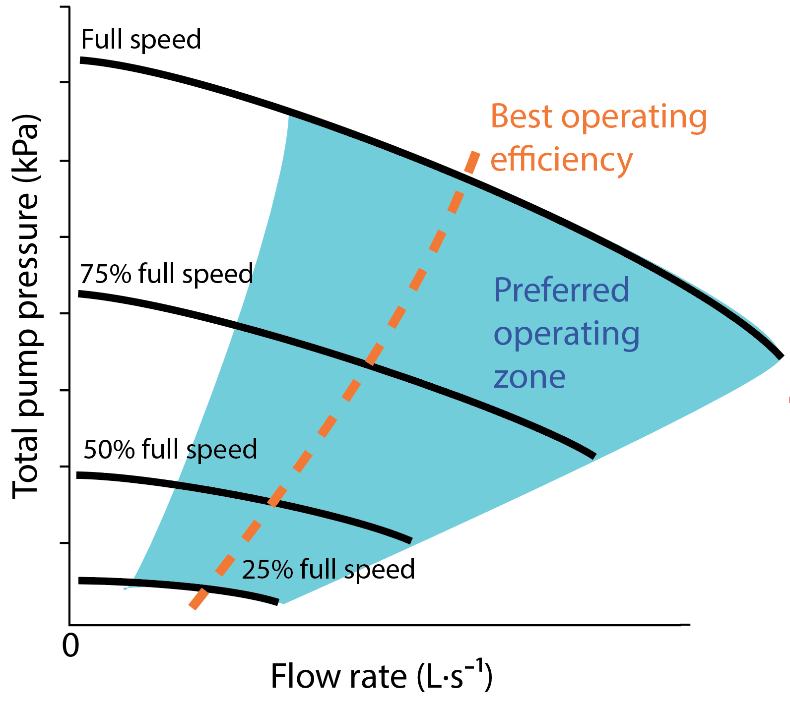
Figure 3: Example variable speed pump performance curves. The most effective operating points are indicated by the orange peak efficiency curve
Fixed speed booster sets, by virtue of their on-off control, create varying pressures that lead to fluctuating flows at the system outlets and pressure surges within the system, with consequent noise and potential damage. Despite the application of buffer vessels, switchgear and contactors can wear quickly as a result of the high number of starts and stops, particularly when demand is low. In tall buildings or large system layouts, fluctuating water demand can lead to pumps regularly stopping and restarting, causing pressure surges throughout the system.
Variable speed pumps deliver a more smoothly controlled water system and, because they employ soft start and stop, the hydraulic and electrical stresses are reduced. Electrical energy consumption is less than when using fixed speed pumps, since they can be operated to meet the load at best operating efficiency more closely.
As with any pump selection for building services, the pump should be selected to operate at high efficiencies for the range of expected pump speeds (typically 25% through to 100%).
So, for example, in the variable speed pump characteristics in Figure 3, the dark blue section is where the pump should normally operate and, ideally, as close to its most efficient operating point as marked by the orange curve. This is possible with carefully considered pump staging and control.

Figure 4: An array of five parallel connected vertical pumps, each with an expansion vessel
Figure 2 shows a small combined break cistern and booster set that employs two submerge variable speed pumps for duty/assist or duty/standby configuration, connected in parallel into a common flow and return manifold. Such multi-pump configurations are typically supplied complete with pressure vessels that allow for expansion and reduced impulse forces. These also act as buffers to prevent the pump set operating on every reduction in the system pressure, and provide a delay between pump ‘start’ and ‘stop’. The vessels will recharge when the pumps are not being fully used to deliver water to the outlets. Expansion vessels fitted to pump sets with variable speed drives are typically smaller than those required on fixed speed pump sets, as they only need to store water for very low flow conditions. To prevent high-pressure overrun when demand is less than the design, a pressure-limiting or variable control flow device is fitted on the pump outlet.
Larger arrays of pumps, such as shown in Figure 4, with discharge and suction manifolds mounted on an anti-vibration base, are supplied in modular form typically with an integrated control panel. Where there are multiple pumps, the minimum recommended flowrate of each pump should be considered and, where necessary, a smaller lead pump may be used. For systems with wide flow variation, the pump controller can automatically minimise energy consumption by operating each pump closer to its peak efficiency, and cascading the operation of the other parallel pumps to ensure that best operating efficiencies are maintained. Multi-pump arrays have inherently higher levels of redundancy, and the smaller pumps, non-return valves and pump isolating valves are easier to maintain and repair.
The vertical multistage centrifugal pumps, as in Figure 4, are likely to be applied in larger and taller buildings, and the modularity provides the opportunity to readily meet the needs of future changes in building use. These are available in many configurations, with different numbers of impellers stacked vertically, and are likely to be able to deliver 2,500-3,000kPa or more. Although pressure vessels are shown mounted on this set, large, floor-mounted expansion vessels are commonly supplied separately for connection to the discharge pipework. These are used in applications such as high-rise accommodation, larger multi-storey buildings, and those with high-pressure requirements.
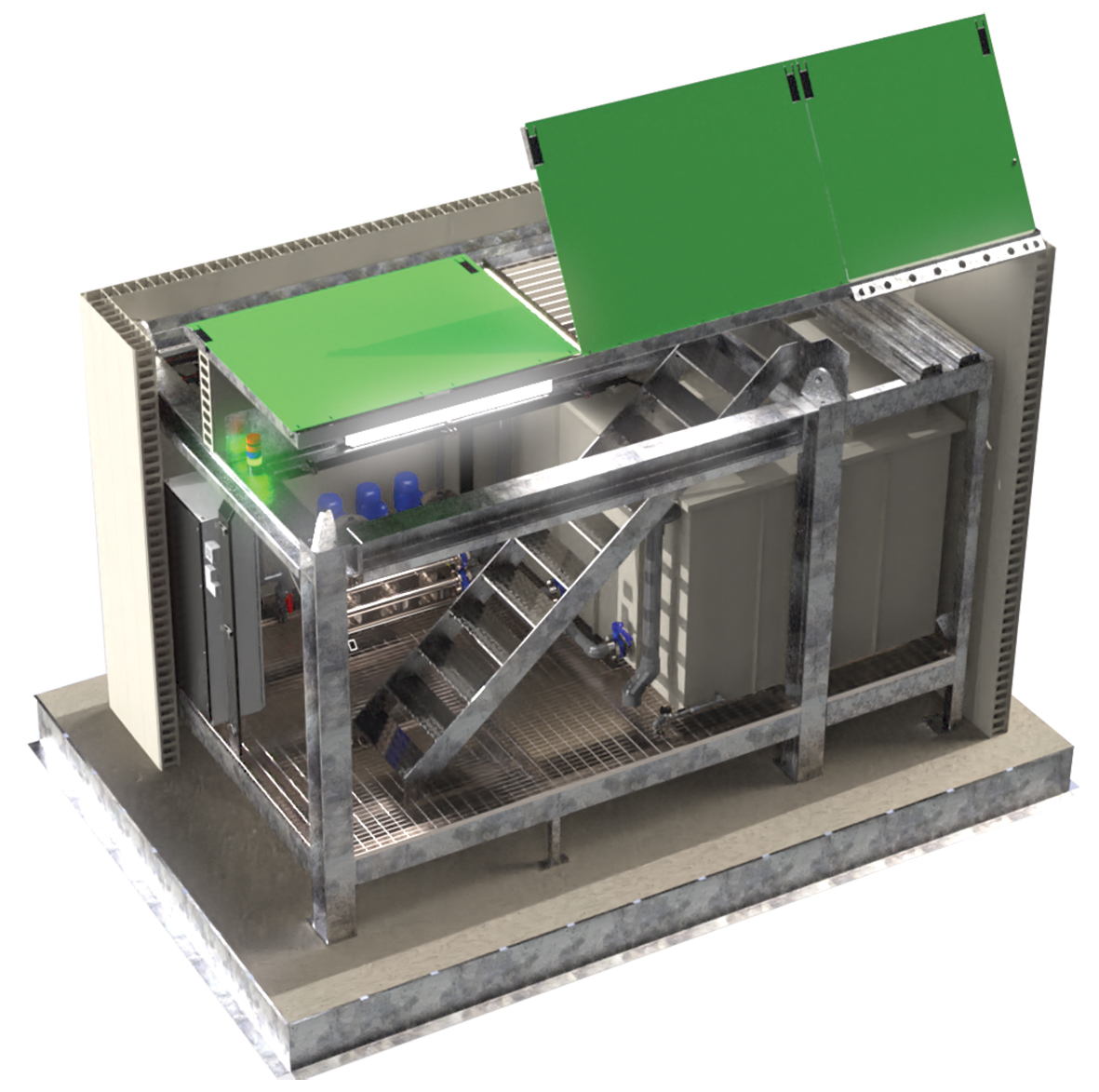
Figure 5: Underground packaged plant room fitted with pump set and break cistern (Source: Dutypoint)
Typically, if a standby pump is required then there is only one available. However, for critical duties it may be considered necessary to allow for more than one unit failing. There may be an advantage in employing all pumps as duty pumps so they can all operate together at the most efficient operating point for the maximum time (as discussed more fully in the May 2019 CIBSE Journal Commercial Heating Special CPD).
Protected, prefabricated enclosures may be used that include a storage cistern and pump set in one space that is located externally to the main building. Such heated, illuminated enclosures can contain other plant such as water treatment equipment, and should be constructed and insulated to moderate heat losses and solar and thermal gains. Similarly, fully prefabricated arrangements are also available that can be located underground, as shown in Figure 5.
Whatever the form of booster set, some suppliers believe it is acceptable to bring together components such as pumps, drives and controls, and rely on the individual items’ CE marking as compliance for the set. As highlighted by the BPMA7, ‘the complete set is a machine in its own right and must therefore have a label affixed with a CE mark and be supported by all the appropriate documentation, including a Declaration of Conformity’.
In assessing the suitability of systems, it is important to consider the range of conditions, including extreme (but possible) operation, such as when the distribution is obstructed and pressures rise beyond those normally expected. As with all building services, appropriate installation and commissioning is key to avoiding operational problems and premature failure. Importantly, this includes ensuring that there is ready access and space for maintaining and exchanging pump set components.
© Tim Dwyer, 2019.
- With thanks to Frazer Ross from Dutypoint for the use of his material in the production of this article.
Further Reading:
CIBSE Guide G: 2014 (2017 revision) Public health and plumbing engineering, chapter 6, sections 1 to 5.
BS 6558:2015 Guide to the design, installation, testing and maintenance of services supplying water for domestic use within buildings and their curtilages – Complementary guidance to BS EN 806 provides very useful system information and layout schematics.
References:
- The guaranteed standards scheme (GSS): summary of standards and conditions, OfWat 2017.
- Water storage tanks and cisterns, UK Drinking Water Inspectorate, 2013.
- The Building Regulations 2010, Approved Document G, Sanitation, hot water safety and water efficiency, Appendix B.
- Plumbing Engineering Services Design Guide, The Institute of Plumbing (CIPHE) (2002).
- An assessment of the validity of the loading units method for sizing domestic hot and cold water services, CIPHE/CIBSE/Heriot Watt Uni/SoPHE 2017.
- CIBSE Guide G, Public health and plumbing engineering, CIBSE 2014 rev. 2017.
- www.bpma.org.uk/news-article/5996faef4f837/EU-Compliance-for-Booster-Sets-is-a-Legal-Requirement – accessed 3 September 2019.