![]()
Surface water drainage carrying rainwater (and melted snow and ice) from gutters and rainwater pipes is collected separately and recycled or, where available, passed into specific surface water sewers. This is discussed extensively in CIBSE Guide G, Public health and plumbing engineering.2
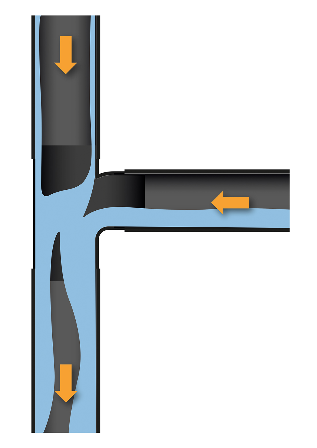
Figure 1: Section through a branch entry to the stack, indicating the disturbance to the downward flow and potentially transient blocking of the air path down the stack
For sizing and determining appropriate piping arrangements for soil (named after the euphemism ‘night soil’) and waste pipes – which are collectively known as foul water drainage – UK installations should conform with BS EN 12056-2:2000 Gravity drainage systems inside buildings. This is referenced by the Building Regulations (for example, as described in AD part H of the England Building Regulations) and other standards appropriate to the particular building application and location. Section 3 of CIBSE Guide G2 draws the information from a number of sources and provides a good reference when developing designs for building water drainage. Products used in drainage systems should conform to the EU Construction Product Regulation and national requirements – for example, in England this is defined in AD 7 Materials and workmanship.3
Foul water is generally defined as waste from a WC or urinal, bidet or appliance used for washing receptacles for foul waste, or water that has been used for food preparation, cooking or washing. When water flows away or is flushed from a fixture, it will first pass through a trap that employs a water seal (normally a water ‘trap’) to prevent gases from drains and sewers from entering the occupied space. The soil and waste pipes – also known as sanitary pipes – carry water discharged through the branch pipework into the main vertical soil pipe, or ‘stack’. The diameter of the branch pipe is determined not only by the fixtures that drain into it, but also by the distance that it runs before joining the main stack.
The foul drainage system typically applied in UK buildings is what is known – in terms of BS EN 12056-2 – as System III. Under working conditions, traps should retain a minimum seal of 25mm of water and, as specified in the national annex to BS EN 12056-2, for UK class III installations, comprise a static trap water seal of 50mm or 75mm, depending on the particular fixture.
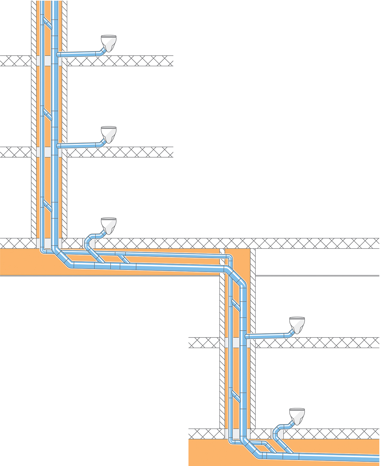
Figure 2: A simple secondary ventilated stack system in a high-rise building with separate dry ventilating stack (Source: Geberit)
The soil stack is continued upwards above the topmost branch (now solely a stack vent) and this combined soil and vent pipe may provide an outlet to vent foul gasses, as well as being a source of vent air to relieve pressure imbalances. Stack vents may be terminated by an automatic, one-way air inlet valve, but at least one stack vent in the building’s system must allow relief of foul gas to atmosphere.
For single domestic applications, small commercial premises and some smaller groups of homes, the guidance in AD part H directly provides the design data to determine the appropriate sizes of sanitary pipework. Larger installations, such as those used in high-rise buildings, are likely to require the more extensive data that is developed in BS EN 12056-2. The stack is typically sized using discharge units (relating to expected flowrates from appliances and fixtures) and a frequency factor that depends on the type of use – for example, house, school, gym, hospital or commercial kitchen. The procedure and calculation method are explained in BS EN 12056-2.
According to Jack,4 the UK ‘has witnessed a consistent simplification of vent system design – from the use of the two-pipe system in the early 1900s through to the use of the one-pipe and modified one-pipe systems in the mid-1900s, and the development of the single-stack system (commonly used since around 1970)’. The one-pipe system is known formally as a ‘primary ventilated stack system’.
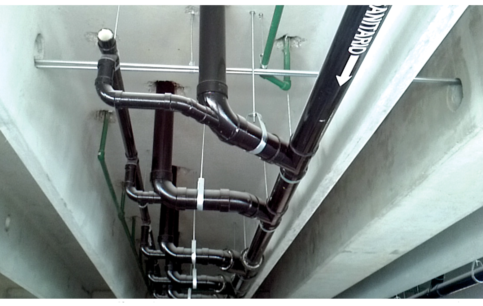
Figure 3: Secondary ventilated stack system installation (Source: Geberit)
The flow down a stack is normally considered as ‘annular’ – a ring of soil water spiralling down the inside surface of the soil stack. As shown by Jack,4 in reality this is not likely to be a simple smooth ring of soil water but, instead, can change shape significantly as it is affected by transients when water enters the stack pipe from the various branches (as illustrated in Figure 1).
As the water flows and swirls down the stack, air is entrained, being drawn down from the top of the stack vent (which is open to atmosphere) and being joined by the air entering as part of the flow from the branches. The flow of fluid from the branches will intermittently interrupt the free flow of ventilating air in the stack, so exacerbating transient pressure variations throughout the stack. If the pressure is sufficiently low, caused by the free flow of ventilating air in the stack being interrupted by branch flows or changes in the direction of the stack, the water seal can be siphoned from the traps.
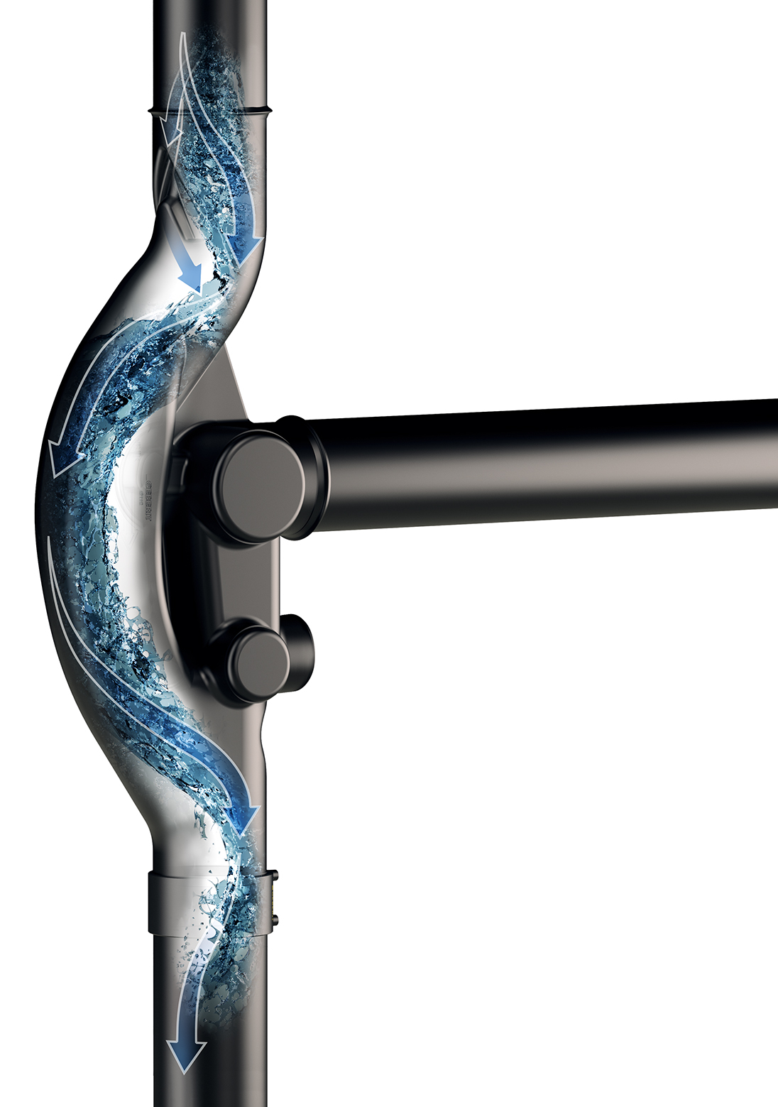
Figure 4: Enhanced geometry branch connection for stack pipe (Source: Geberit)
A positive pressure at the base of the stack is caused by the entrained airflow being impeded by a water curtain formed at the point of separation of the water downflow from the pipe inner radius, and by restrictions in the downstream system. A positive pressure at the base of the stack may compromise (and even ‘blow out’) the trap for branches close to the base, so BS EN 12056-2 limits how closely a branch waste pipe can connect to the main discharge stack, relative to the base of the stack.
A significant element of the system design process is to ensure the integrity of all water seals, and so prevent foul gases entering the occupied space. Although trap seal loss by suction pressure can be avoided by strategic positioning of mechanical devices such as automatic air valves (AAVs) and waterless traps, these effectively act as closed ends when subject to positive pressures and, therefore, are not able to relieve these positive transients. As suggested by Jack,4 these devices have the potential to make the magnitude of the positive transient worse, as they can increase the local airflow velocity halted by the water curtain at the base of the stack.
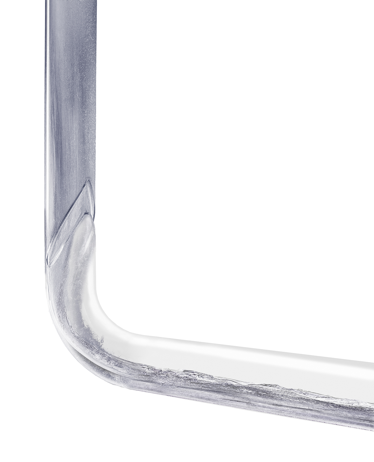
Figure 5: Enhanced geometry vertical to horizontal bend (Source: Geberit)
Transients are particular challenges for multi-storey installations where there can be significantly variable flows from branches, particularly in high-rise buildings where the pressure variations are made more extreme by the numerous and diverse branch connections. To help overcome this, the two-pipe system – formally known as a ‘secondary ventilated stack system’ – is often employed, where one pipe is a dry ventilating stack used to supply air at intermediate points to the soil stack (as illustrated in Figure 2). Detail and further descriptions of these systems, and variants, are provided in CIBSE Guide G and BS EN 12056-2.
Despite the tried and tested nature of such systems, however, they require significant amounts of pipework and space, as shown in the relatively simple example of Figure 3.
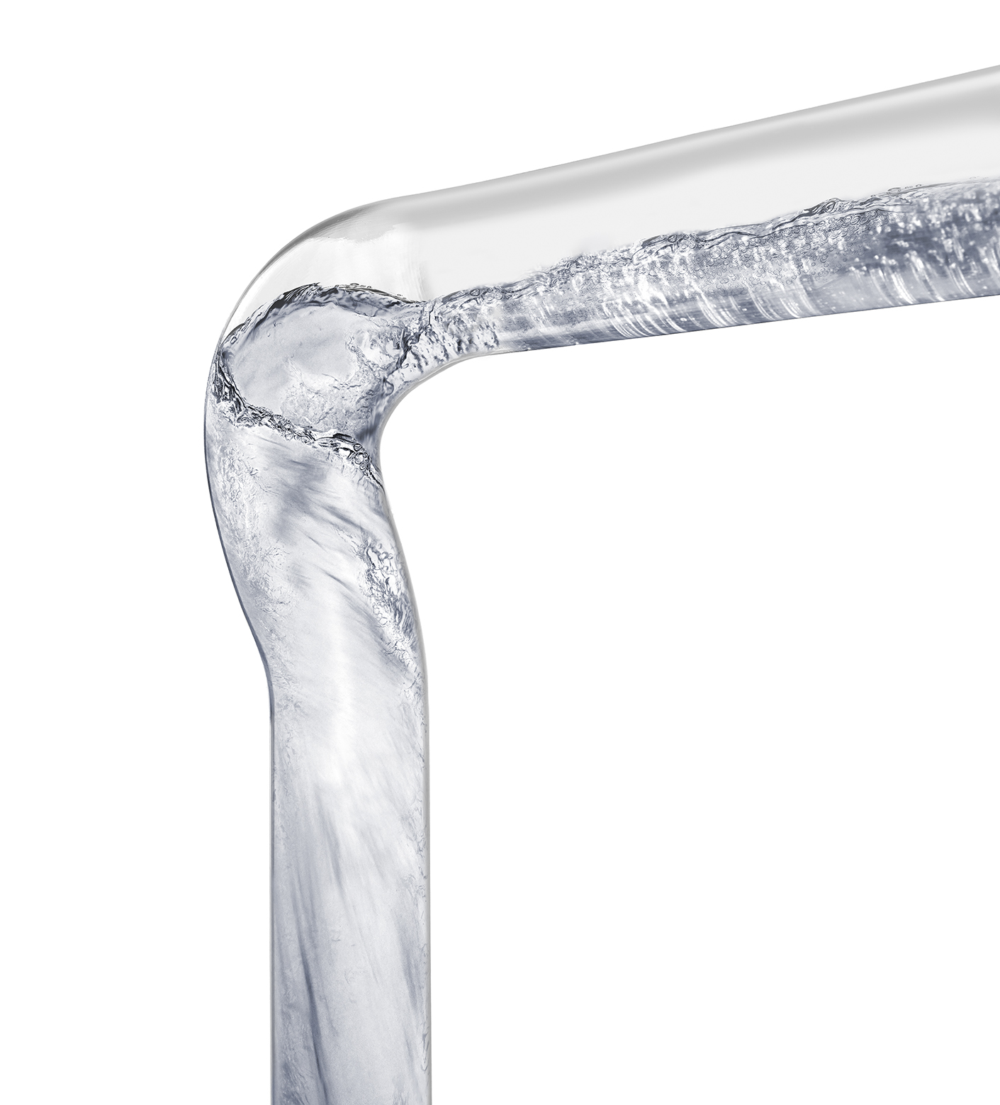
Figure 6: Enhanced geometry horizontal to vertical bend (Source: Geberit)
Proprietary systems have been developed that allow branch flows into the main stack without impacting the main downward flow or interrupting the air path. An example of such an enhanced geometry branch fitting is shown in Figure 4.
As the downward flow enters the fitting, a flow divider breaks the annular flow so that, while the flow changes direction in the curve of the fitting, a clear air path is maintained. The smoothly shaped internal profile reinstates the swirl as the water leaves the fitting, and so annular flow passes down the stack. The flow divider allows the main downward flow to continue without being adversely affected by the incoming branch flow, and the rotating movement allows the water to flow around and down the pipe wall, allowing a continuous column of air. The separation of the branch connection from the main flow of the stack maintains airflow, and avoids the negative pressures that may adversely affect water seals. A manufacturer reports that this effect increases the discharge rate of a 100mm fitting potentially by more than 70% (from 6.8L·s-1 to 12L·s-1). Such branch fittings may be applied in UK installations to obviate the need for a separate ventilating stack, but any offset in the stack will need a ventilating bypass to maintain the open air path. There is increasing application of enhanced geometry fittings to ensure a continuous stack air column with no need for a ventilating bypass.
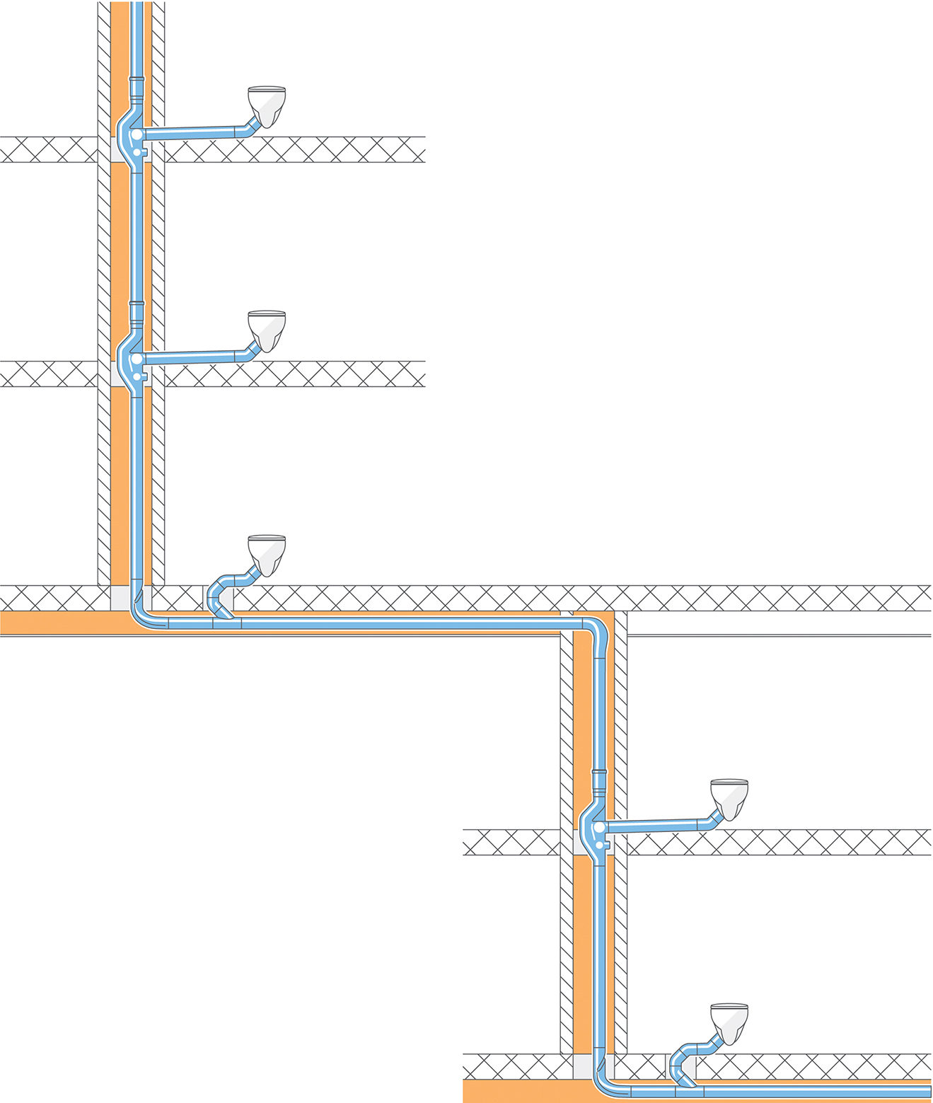
Figure 7: A single soil and vent pipe employing enhanced geometry bends and branch fittings to ensure that the air path is maintained throughout the stack (Source: Geberit)
When the water comes to either an offset or the base of the stack, the water flow transfers to the horizontal. In a conventional bend (standards recommend two 45-degree bends, plus a connection pipe), the flow can break away from the pipe surface and impede the flow of air. The enhanced geometry bend (as shown in Figure 5) employs a flow divider to push the flow of water to the far side of the pipe and then into the guide channel, which maintains the airway as the water transforms to a layered flow. It also assists the flow by reducing impulse losses and, therefore, maintaining the velocity of the water along the near horizontal. As the water flow transfers back to the vertical, following the horizontal run of an offset, the air passage can again be impeded in a traditional, plain bend. The enhanced geometry bend (Figure 6) uses the smooth profiled moulding of the bend’s inner surface to reinstate the swirl and provide the transition from layered flow without blocking the passage of the air, while maintaining almost all of the kinetic energy.
As illustrated in Figure 7, such systems can reduce the drainage space required in high-rise buildings by eliminating the need for the ventilating stack, and – if incorporated at an early design stage – could increase the usable floor area. This can also increase the available space under the soffit, so easing the routing of other services and, potentially, allowing more room space or reducing the required storey height.
While high-rise buildings (for example, those of 15 floors or more) increasingly dominate cityscapes in the UK, there are no standards that are specifically applicable for systems in such buildings. In the void left by the lack of specific standards, various manufacturers are bringing new solutions to the market as they identify a need and as the market demands. These can enable more effective systems, but building designers and owners are reliant on the experience of manufacturers and certifications of individual products for bespoke solutions, rather than being able to benefit from standards.
© Tim Dwyer, 2019.
References:
- England Building Regulations 2010 Approved Document H Drainage and waste disposal, NBS, 2015.
- CIBSE Guide G Public health and plumbing engineering, CIBSE, 2014.
- England Building Regulations 2010 Approved Document 7 Materials and workmanship, NBS, 2013.
- Jack, L et al, The generation of positive air pressure transients in building drainage vent systems, Int symp water supply and drainage for buildings, 2002.