![]()
This article will consider how, with appropriate analysis and control, parallel pump systems can be implemented to maintain reliable service in HVAC systems and operate more efficiently than traditional, duty-standby arrangements.
As comprehensively discussed in CIBSE TM56,1 life-cycle resource efficiency should be an integral part of every building design. As pumped circulation water systems are in practically every serviced building, and will use a significant proportion of operating resources, they are prime candidates for attention.
So it is essential that appropriate consideration is given to the design of both the pipe network (materials, velocities and resulting pressure drop) and the pumping systems that provide the motive force for the water circulation.
‘Redundancy’ has traditionally been used in building services to refer to the level of back-up equipment, or system, that is available in case of a full, or partial, system failure. There is no simple formula to determine what redundancy should be included in a system. It is a matter of assessing the risks, and evaluating the acceptable minimum level of service and the impact of full, or partial, failure, weighed against the resources required to provide a means of protection.
It may be tempting to add high levels of redundancy for every project; this will not always be sustainable or necessary, however, and will depend on many, often dependent, factors.
For example, in a climate with few cooling hours, a redundant chiller is difficult to justify based on thermal comfort alone. In contrast, in many climates, a hospital would consider redundant chillers, boilers and pumps as normal practice.
The availability of onsite technicians will also affect the impact of failure on the building users – fewer trained onsite technicians encourages the adoption of increased levels of equipment redundancy.
Historically, constant speed pumps – and constant-flow distribution systems that employed diverting control at the load – were the norm, so the pumps were selected to operate most efficiently at the flowrate able to meet the continuous maximum demand. Variable-flow networks and associated variable-flow pumps were rare, so it made good sense to operate pumps alternately at 100% design on a ‘duty-standby’ arrangement.
So installing two pumps in parallel – with one pump selected to give full design flow and a second to provide a complete backup – is common in many building projects, regardless of their sensitivity to failure. It is typical, in this duty-standby installation, to alternate the active duty pump on a timed basis to even out the wear on both pumps. In the event of one of the pumps failing, the standby pump takes over the duty.
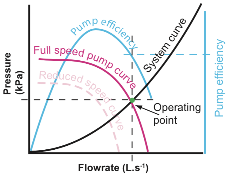
Figure 1: A simple closed-loop pump system operating point
The pumps are each likely to have a pressure-flow characteristic similar to that shown in Figure 1, where the system curve represents the characteristic of the pipework system. The pressure drop through the system, ΔPdesign kPa (or ‘head’ in metres water) is determined as part of the design process for the pipework system at a flowrate, Qdesign L·s-1, that is required to meet the design loads.
The system curve is then produced for a range of flowrates using the relationship that ΔP α Q2. The pump curve is a function of the pump geometry and would be provided by the manufacturer. The operating point indicates the flowrate (and system pressure drop) if a specific pump, operating at a particular pump speed, is installed in the system. Ideally, a pump should be selected so that its operating efficiency is high when the pump is operating in the system.
When the speed of a pump is reduced, the shape of the pump efficiency curve will typically maintain approximate correspondence with the shape of the pump characteristic, but manufacturers’ data will be able to offer more accurate detail.
To prolong pump life, a pump should be selected so that it does not operate consistently towards the left end of the pump curve, where the flow is very low and the pressure is high.
If two identical pumps were running at the same time – and same speed – in parallel (such as in Figure 2), the flowrate will be twice that of one pump operating on its own particular generated pressure. (By comparison, if the two pumps were operated in series, then the flowrate would remain the same as for one pump, but the generated pressure would double.)
If this parallel pump arrangement is used so that both pumps concurrently share the flow, then each of the pumps would be smaller than the equivalent duty-standby arrangement as, at full flow, each one would be responsible for delivering just half the design flowrate.
These pumps are likely to be physically smaller than the duty-standby pumps that they replace, so will be lower-cost units and have less embodied carbon.
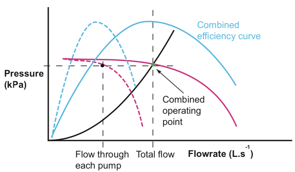
Figure 2: Two pumps operating in parallel arrangement
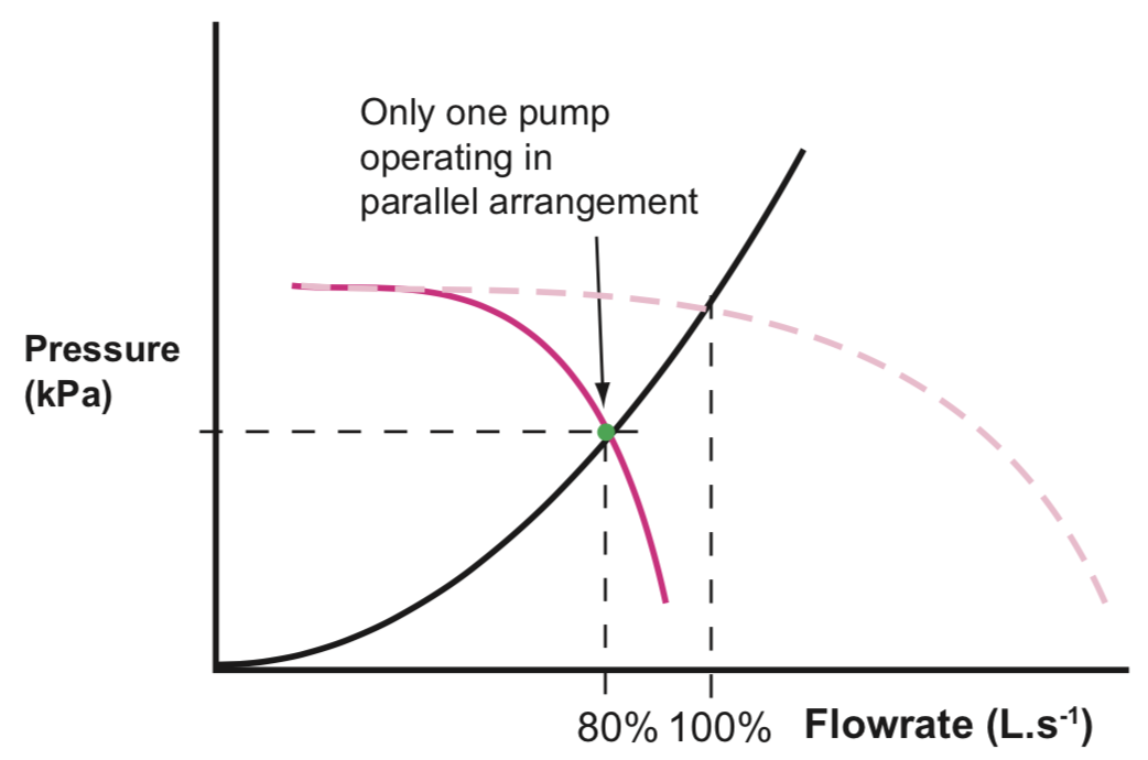
Figure 3: Single pump operating in parallel arrangement (one having failed)
If one of the pumps fails, leading to just one of the parallel pumps operating, it might be assumed, erroneously, that the single pump operation would deliver 50% design flow.
However, considering the operating point in Figure 3, due to the shape of the system characteristic and the particular pump characteristic, this example would still be able to deliver 80% of design flow; for comparison with more traditional descriptions, this is known as having ‘80% redundancy’.
At most times, commercial HVAC systems operate at part load. For example, considering monitored installations in central London, the demand exceeds 80% for less than 3% of the operating hours.
So if one pump were to fail (in a dual-duty pump application), it would only potentially impact on building operation if it coincided with that 3% of the occupied period. In any case, there would still be 80% of maximum design flow – so not a complete system failure – even if it was to fail in the peak 3% hours.
For a chilled water system, the cooling coil output characteristic is such that 95% output would be delivered to the air at 80% water flowrate, although the dehumidification at the coil will be less than design, as the mean coil temperature will be higher. Heating coils have a similar, and slightly greater, proportional heat output at 80% flow.
In practice, there are likely to be considerations that increase this redundancy factor – so reducing the risk. For example, building chilled water systems are likely to have a ‘safety factor’ added to the system design pressure drop (around 10-15%), and when variable speed pumps are selected, they often have excess speed capacity that could be used when one of the pumps fails or is taken out of service.
Together, these factors may increase the redundancy by 5% and so reduce the potential hours when failure of a pump may impact the building operation. In the case of the London office example, it would bring this down to approximately 1.5% of occupied hours.
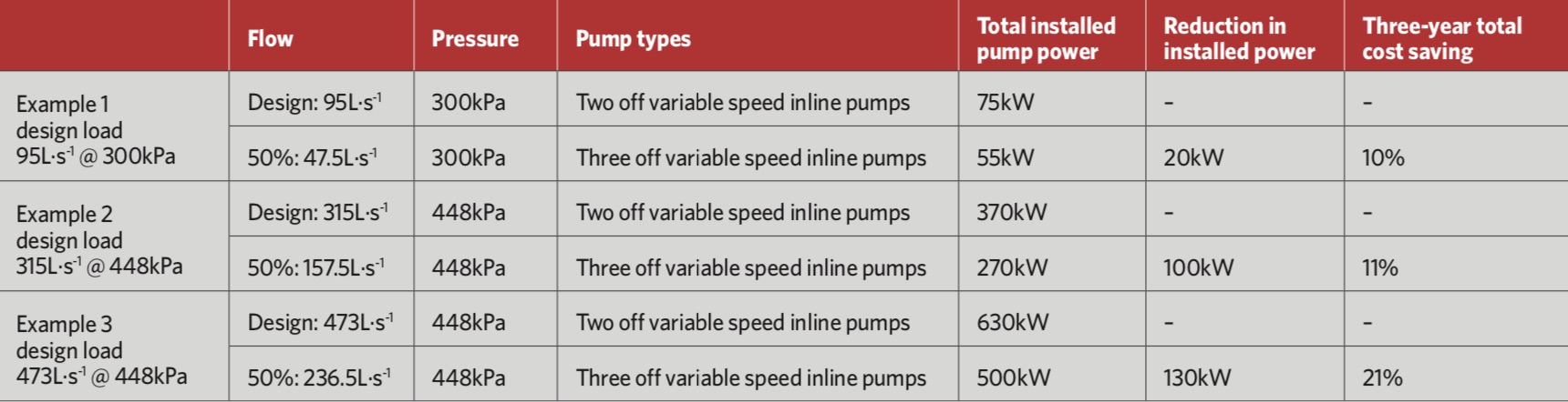
Table 1: Comparative three-year cost of installing and operating three duty parallel pumps, compared with a two-pump, duty-standby arrangement in example applications (Source: Armstrong)
There are many applications where less than 100% redundancy is unacceptable. However, non-critical HVAC installations – such as those serving teaching spaces and apartment blocks, and where there are particularly restrictive budgets – typically do not have any redundancy, and, in the event of a failure, it may take some time to repair or replace parts.
Historically, this type of application may have been installed with a single duty pump, but there may be an opportunity to re-evaluate the benefit of a parallel duty-pump arrangement to give a reasonable level of redundancy.
For high reliability, or comfort-sensitive installations – such as hotels, offices and shops – the HVAC is not essential to business operation, but a failure would result in uncomfortable guests, office workers or shoppers, and would be inconvenient and, possibly, costly. Such a scenario would be an ideal candidate for the redundancy offered by parallel duty pumps.
For critical installations, the HVAC system is considered essential to the primary activity and requires redundancy of 100%.
An option that is commonly employed, as an alternative to a duty-standby pump arrangement, is to use three pumps and size each for 50% maximum flow – the premise being that, should any one pump go out of service, 100% redundancy is still assured.
Using data as provided by a manufacturer in Table 1, there are potential financial advantages with this arrangement – this cost saving was calculated based on the capital cost of the pumps and subsequent operation for three years.
The greater the system flow, the larger the potential three-year total cost savings. Greater savings may be shown in new installations if the need for concrete plinths for the larger duty-standby pumps had been negated by the 50-50-50 arrangement employing smaller vertical inline pumps. If the total system flow is higher than 315L·s-1, then a four-pump configuration – each pump sized for 33% flow – should be considered.
When adopting parallel duty pumps, it is important to consider the staging methodology for the pumps. This ‘best efficiency’ staging approach is preferable where, as the required flowrate varies, pumps are ‘staged on’ and ‘staged off’ based on the best overall combined efficiency.
So, for example, in a two-pump parallel system, one pump would operate to deliver low flowrates and, as the load demands greater flowrates, the second pump would ‘stage on’ when the efficiency of the two operating together is greater than the single pump operating alone at a higher speed.
Controlling pumps in this way enables higher efficiencies over the load profile of the system, and it prolongs the life of the pump, as it will be operated away from the left side of its curve.
The traditional, less-efficient, approach – as is typical in building management system (BMS) control – is based on pump speed, where pumps are staged on at around 95% of full speed and off at 55% speed.
When considering parallel pumping, the means of controlling the pumps can affect not only the energy efficiency of the system, but also its reliability. Typically, parallel pumps are controlled using either a BMS or dedicated pump controls. There are likely to be more sophisticated – and, possibly, more accessible – controls from the pump manufacturer that may include:
■ Best efficiency staging control
■ End-of-curve protection
■ Auto pump sequencing
■ BMS connectivity for alarms and performance monitoring
■ Pre-configured algorithms for standard applications, including variable primary flow control.
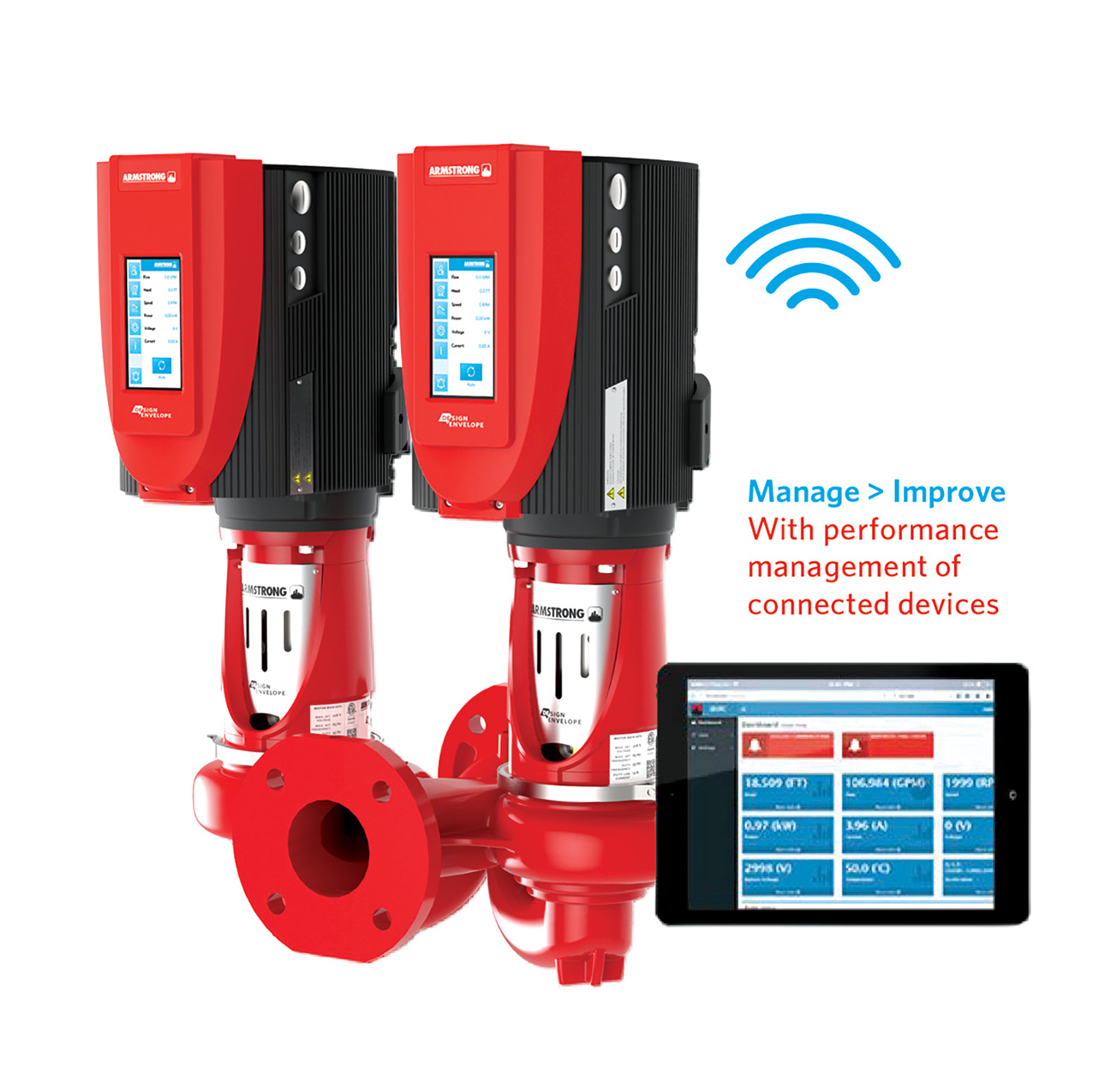
Figure 4: Pumps with integrated touchscreen that wirelessly link through to cloud-based interfaces, such as smartphones, for set-up, monitoring, control and alerts (Source: Armstrong)
Increasingly, the availability of ‘intelligent’ controls, using local and internet cloud-based processing, is enabling condition-based monitoring, optimised control and data collection.
Some manufacturers are able to supply pumps with controllers that use integrated, pump-mounted, touch displays (such as in Figure 4) to give local feedback and communication with local BMS and cloud-based data services.
As well as providing commissioning engineers and operating teams with real-time operational information, the diagnostic software is able to warn of events such as excessive vibration, ‘deadhead’ (obstructed flow) and failure of impeller/motor coupling.
By accessing the processing power and databases held in the cloud, more sophisticated analysis will soon be available, such as predicting failing bearings, identifying imbalance in the impeller and alerting operators to pump cavitation.
© Tim Dwyer, 2019.
REFERENCES:
1 CIBSE TM56 Resource efficiency of building services, CIBSE 2014.