![]()
Many heating and cooling loads in commercial and industrial buildings can be controlled by varying the water flowrate – notably heating and cooling coils in air-handling systems, fan coil units and chilled beams. This so-called ‘throttling’ control will affect the total flowrate being circulated around the system and so, if there is an appropriate control mechanism in place, can significantly reduce the energy consumed by the pump.

Figure 1: Energy saving through variable speed pumping. As demand for heating or cooling water drops, so does the pump power as its speed is reduced
The more traditional solution was to use a three-port diverting arrangement that controlled the load but did not reduce the overall flow through the main distribution pipework and the pump. In heating systems, the return water temperature increased at low loads, so reducing overall system effectiveness and making it less likely to be able to operate boilers in (the more energy-efficient) condensing mode. In cooling systems, the temperature of the return water would drop towards the flow temperature as the cooling load reduces, so not using the full benefit of the chilled water. By applying two-port control valves at the terminal loads – and so not diverting flow around the loads – the main distribution flowrates will modulate to give the total required flows that meet the sum of all the branch flows. As the pump power is proportional to the cube of the flowrate, this gives an opportunity for reduced pumping power, as well as maximising the temperature difference across the system and improving the exergetic performance.
PICV guidance
The diagrams and explanations in this article are focused on specific aspects. For detailed PICV design and installation guidance, refer to the references and bibliography in CIBSE Knowledge Series 71 (and supplement), as well as manufacturers’ literature.
There are a number of technologies that have been used to achieve operational savings in pumping variable flowrates. However, the maturity of low-cost, electronically controlled (‘inverter’ or ‘variable frequency’), variable-speed, motor-driven pumps has led to the widespread application of variable flowrate heating and cooling water distribution systems.
The example pump performance, as shown in Figure 1, indicates a system where – as the system requires less flow – the pump speed can be gradually reduced to provide the operating points. Three example operating points are shown at nominal maximum, medium and low speeds. Pump power is clearly significantly lower as the flow reduces.
Typically, each separate branch serving a load will have an element of fixed resistance to flow that comprises a balancing device, isolation valves, flow-measuring device and the heat-transfer surface that makes up the load itself, plus a variable resistance provided by the control valve. As the – potentially numerous – two-port ‘throttling’ control valves individually modulate (so altering their resistance to flow), the relative pressures will change across all the separate system branches as the flow modulates in the main pipework distribution network. This will erratically alter the available pressure that drives the flow through any particular branch, making it challenging to offer stable, controllable flow at all terminal loads.
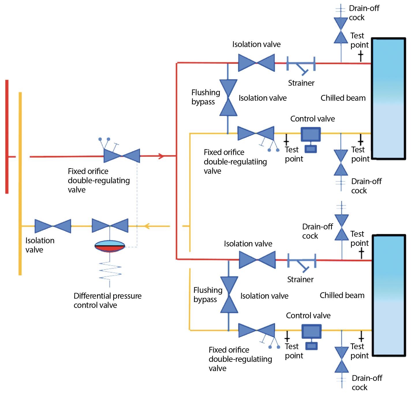
Figure 2: Simplified example of using a DPCV to moderate the pressure perturbations in a sub-network of two chilled beams (Source: based on Hattersley diagram)
To overcome this, the automatic differential pressure control valve (DPCV) has been applied typically to branches supplying several individually controlled loads, such as in the example in Figure 2. The DPCV contains a diaphragm that separates two chambers in the valve; in this example, one chamber is connected (internally) to the valve inlet and the other, via a capillary tube, to a tapping in the double-regulating valve in the flow pipework. An adjustable spring-loaded valve spindle is connected to the diaphragm, closing the valve when differential pressure rises and opening it as differential pressure falls. This effectively isolates the sub-circuit from variations in the main system pressure, and is a widely applied solution. It can be challenging to select the correct DPCV size for systems, and the individual two-port control valves in the sub-system can still be adversely affected by pressure variations – and will, in any case, require separate balancing. However, this arrangement is particularly useful where there are likely to be very low flowrates or where there is a high differential pressure across the main distribution flow and return pipework.
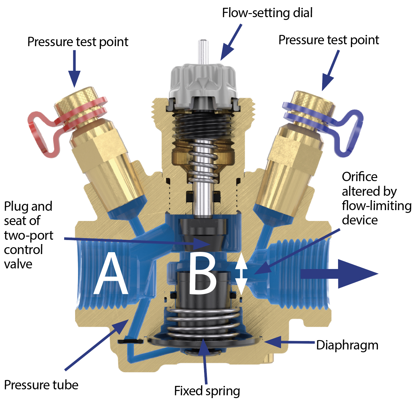
Figure 3: A section through a pressure-independent control valve
As described in detail in CIBSE KS7 Supplement,2 the PICV integrates the function of a DPCV together with a balancing valve to limit the maximum flow, as well as providing modulating control.
As illustrated in the section through a PICV in Figure 3, the key element that makes a PICV stand out from other control valves is the integral diaphragm that has differential pressure across the control-valve inlet and outlet. The specific internal configuration varies between manufacturers; however, the movement of the diaphragm (working against a spring) drives a flow-limiting device (as shown in the diagram, altering the space indicated by the white arrows) to maintain a (practically) constant differential pressure between A and B. So – for example, as the system pressure increases at point A relative to the pressure at B, because of valves closing or the pump varying its speed – the action of the diaphragm further restricts the flow and lowers the effective differential pressure across the control valve. The constant pressure difference between points A and B effectively maintains a consistently high valve authority at all loads, so assuring good controllability across the operating range of the control valve.
A flow-setting dial, which is usually marked with flowrate (or calibrations), is used to set the maximum design flow during commissioning. Some valves have a specific flow regulator to enable the maximum flow through the valve to be set (in the same way as a separate balancing valve). However, most commercial valves – as with the one illustrated – are designed to limit the maximum control valve opening in place of a separate flow regulator; this will potentially impact the valve turndown, as it will reduce the effective travel of the valve, but this is somewhat compensated by the maintenance of constant pressure across the valve. When the two-port control valve is used for flow regulation as well as flow control, it will be adjusted – using the flow-setting dial – during system commissioning until the maximum design flowrate is achieved, then the remaining valve travel will be used for modulating control. (The valve can be manually operated by rotating the flow-setting dial.)
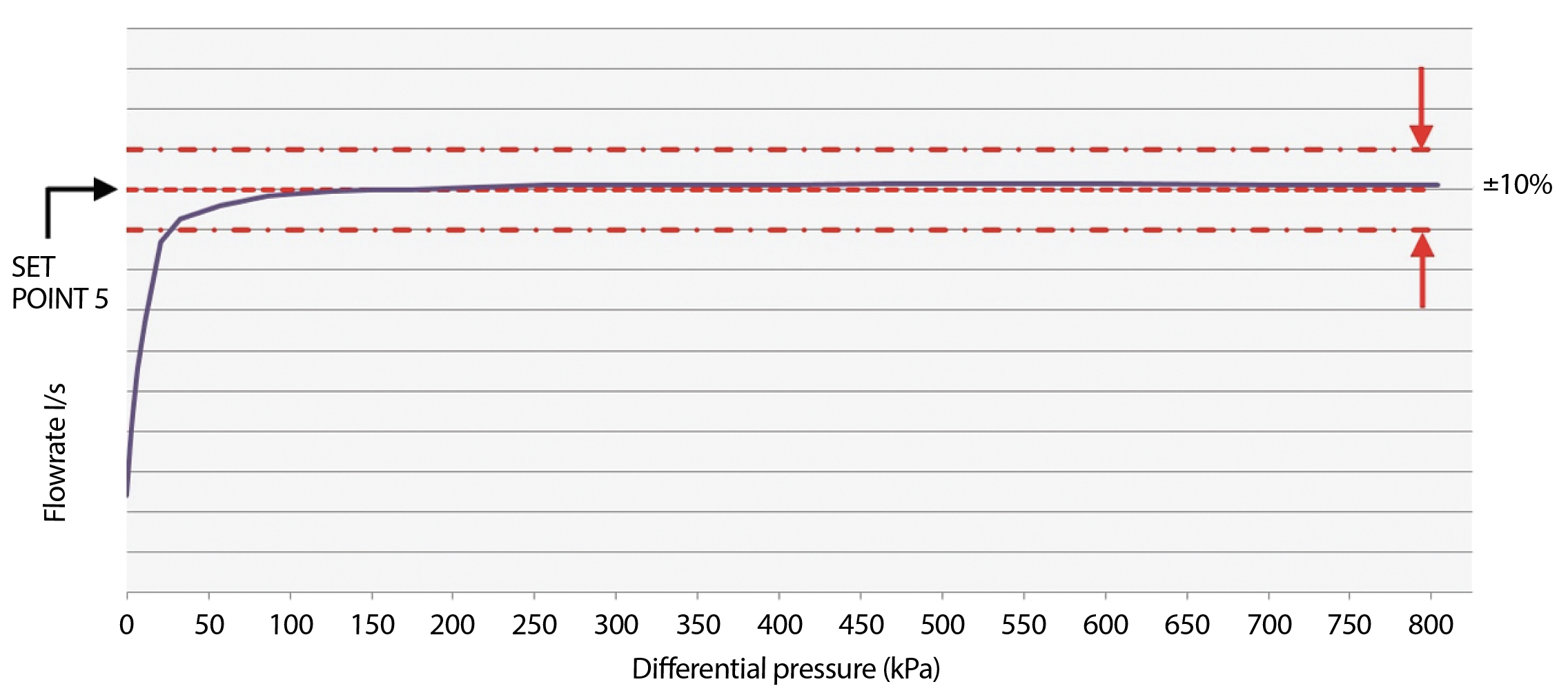
Figure 4: Example of the operating stability of a commercial PICV (Source: Hattersley)
The combined action of the integrated components in the PICV is capable of very stable control across a wide range of pressure differentials, as shown in the measured flowrate in the example valve in Figure 4.
When controlling ducted heating and cooling coils, the control delivered by the actuator to the valve is more consistent if the control valves have a water-flow characteristic that complements the load characteristic from the coil.
Equal-percentage control characteristics are typically used for variable flow applications in building services applications, as an appropriately actuated equal-percentage control valve will complement the heat-output profile of a coil. This results in a percentage valve stem position that is proportional to the percentage coil output. As with any valves, the characteristic of the PICV will alter with valve authority. As a PICV will maintain a typically high valve authority, the characteristic is maintained. However, some small valves will not maintain linearity at low flows.2
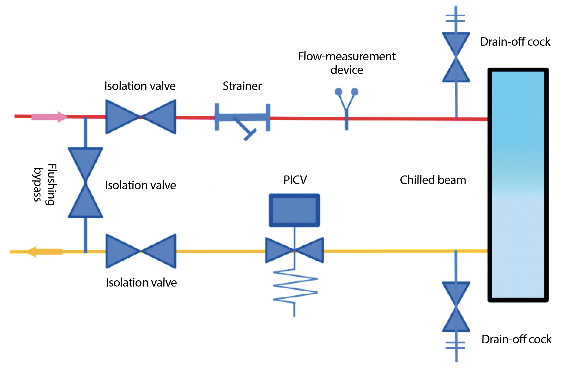
Figure 5: Example of PICV control of a chilled beam (Source: based on Hattersley diagram)
The PICV can be installed – as in the example shown in Figure 5 – where, in smaller systems, it will remove the need for a DPCV and simplify the installation and commissioning process.
Figure 6 shows part of a system layout incorporating PICVs and the accompanying components that are required on connecting branches. Pump-speed control is effected using a differential pressure sensor across the sub-system feeding to the most remote group of terminal units (the ‘index’). In systems with multiple sub-systems (with potentially different load patterns), additional sensors might be required on other sub-systems. There are opportunities with some building management systems to use a position signal from all the individual PICVs to control the pump speed to optimise operation so that all terminals are supplied using the least power. The four-port valves (effectively three-port valves with built-in bypass and connecting ‘T’) in Figure 63, at the end of each sub-system, are used to ensure that the pump will maintain a minimum of approximately 20% flow even when there is no terminal demand.
The selection of PICVs is based on the design flowrate. There are practical limitations of minimum controllable flowrates, as well as the minimum required operating pressure, so it is important that a PICV is selected to operate effectively across the range of expected loads. If the operating differential pressure is too low, the differential pressure spring remains in an uncompressed state, and if it is too high, the spring will be fully compressed – in both cases, it will not maintain appropriate control of the pressure differential across the control valve. In the case of large systems where there are numerous sub-systems, selective application of DPCVs in branches may be needed to limit the maximum differential pressure across the PICVs. However, as shown in the example in Figure 4, commercial PICVs are capable of maintaining control across a wide range of operating pressures.
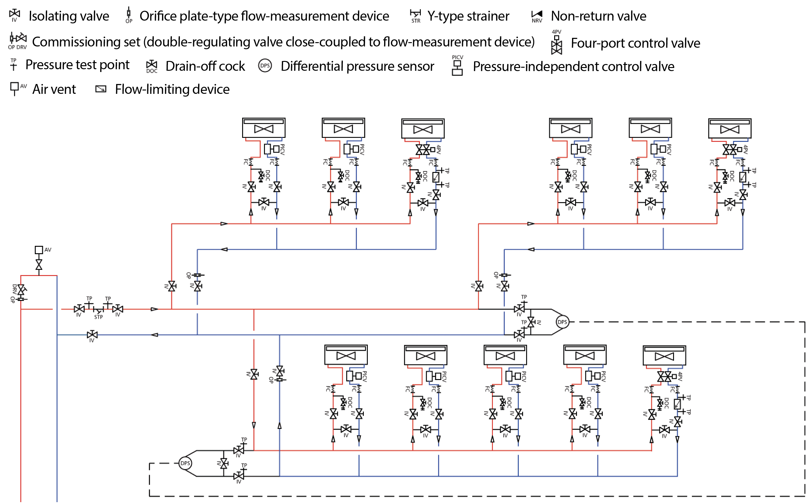
Figure 6: Example of sub-system of a variable flow distribution system (Source: CIBSE KS7)
A significant benefit of PICVs is that they obviate the need to proportionally balance the system because of the integrated differential pressure control. PICVs are simply set to give the required design flowrate using the adjustment on the valve. When commissioning a system, the pressure at the test points (integrated into the PICV body) will be checked – at least in the index of each sub-system – to ensure that the operating pressure differential is within the manufacturer’s specified limits. That means that at maximum flow, with all branches drawing design flow, the ‘least favoured’ (index) PICV has – at least – the minimum required differential pressure to operate (this may be checked using the tapping points on the PICV).
If this pressure is available at the index PICV, then all other PICVs will have greater differential pressure available and so will be able to operate. The CIBSE Commissioning Code W4 requires that the flowrate be checked for each load; this is normally determined using a separate orifice valve (the integral PICV test points cannot be used to determine the flowrate through the valve) – this is indicated as the flow-measurement device in Figure 5.
© Tim Dwyer, 2018.
References
- CIBSE Knowledge Series KS7 Variable flow pipework systems, CIBSE 2006.
- Supplement to CIBSE Knowledge Series KS7 Variable flow pipework systems: valve solutions, CIBSE 2009.
- BG 12/2011 Energy Efficient Pumping Systems – A Design Guide, BSRIA 2012.
- CIBSE Commissioning Code W: 2010 Water distribution systems, CIBSE/BSRIA 2010.