![]()
The amount of heat extracted from water distributed around heat networks will impact on pumping power and heat-generation performance. This will affect both the capital and operating costs. For example, Figure 1 (taken from the London Heat Network Manual1) indicates the impact of network temperature differential on the cost of associated pipework systems. The temperatures selected are also likely to affect the efficiency of the heat source – particularly for heat pumps and steam-turbine extraction – and the volume of any thermal stores. Even if the heat supplied to the heat network is produced from fuels that are carbon dioxide (CO2) neutral, the power used for pumps and fans, and its production, contributes to CO2 emissions. Reduced costs are in the best interest of both the supplier and the consumer, so it is important that the district heating distribution network is holistically designed, operated and maintained for economic and environmental reasons.
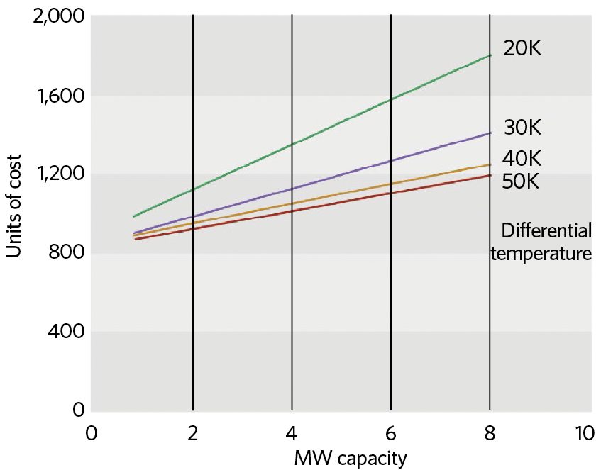
Figure 1: Indicative relationship between cost of pipework infrastructure and differential temperature on a system1
The requirements for each application will need careful assessment, not only with a view to optimising the network temperatures, but also to determine any otherwise unexpected impact on the effectiveness of individual consumer systems. As many new heat networks will supply existing buildings and subsystems, the flow and return temperatures required to satisfy the original heating and hot-water systems at peak load will need to be assessed. This would generally require not only metered information, but also a properly informed site inspection to collect numerical data and explore opportunities to meet demand with (typically, at least) reduced return temperatures – and, hence, lower average system temperatures. Inevitably, in many cases, this necessitates multiple inspections, as there may be seasonal or varying occupational demands – particularly in multi-tenanted buildings, as individual end-user heat demands may not be immediately obvious.
The network temperatures should be planned to take account of these demand variations, if appropriate, by varying supply flowrates. (It may be more challenging to identify ‘seasonal’ requirements where there is a need to satisfy any commercial/industrial processes.) Network losses will be significantly influenced by both the temperature profile and the flowrates.
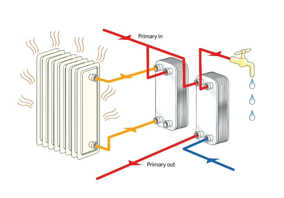
Figure 2: Simplified visualisation of the connection of parallel-connected consumer systems to the heat network primary flow (Source: Swep)
The current version of the CIBSE/ADE publication CP1 Heat Networks: Code of Practice for the UK recommends that the ‘targeted difference between flow and return temperatures on the primary heat network under peak demand conditions shall be greater than 30K for supply to new buildings and greater than 25K for existing buildings (where feasible), to reduce the capital costs of the network, unless a detailed analysis of life-cycle costs and performance shows otherwise’. By comparison, in Sweden – where heat networks are long-established – the requirements for system temperatures are rather more demanding; networks for residential applications require supply temperatures of 65°C,2 with the return water temperature (dependent on the final consumer hot-water system) of between 22°C and 25°C. This sets a standard for at least a 40K difference between flow and return temperatures on the primary heat network.
It is important that delivering useful economic heat safely and reliably to consumers is not obfuscated by an over-zealous desire to reduce heat network costs. There may be demands – such as legionella control, thermal performance of materials, legacy comfort systems and processes – that are particularly sensitive to flow, return or average water temperatures.
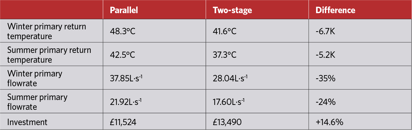
Table 1: Example of greater temperature difference for traditional parallel, compared with two-stage, substation
Many district heating schemes operate at temperatures and pressures that are compatible with typical building services. In this case, consumers’ heating systems can be connected directly to the district scheme, with the same water that flows in the district network flowing through consumers’ heating circuits.3 However, where there is a desire to decouple the consumer systems from the heat network – or where the network flow temperatures are higher than those required in the consumer systems – thermal substations are used to provide a reduction in temperature (and pressure) so that the network heat can be safely used in the building. The substation typically consists of a plate heat exchanger that acts as a pressure break between the district network and consumer system. The heat exchanger often forms part of a metering station – with flow-control valves, isolation valves and a heat meter – that acts as the demarcation point between the district scheme and consumer systems.3
Substations in heat network installations are typically arranged in either a parallel or a two-stage arrangement. A parallel connection, as visualised in Figure 2, uses separate heat exchangers for space heating and domestic hot-water systems, and the water from the primary (heat network) is cooled only once, in a traditional parallel system. In a two-stage arrangement, as in Figure 3, the return flow from the radiator heat exchanger is mixed with the flow from the after-heater. The mixed flow enters a third heat exchanger, the preheater, the principal purpose of which is to preheat the cold water before it enters the after-heater – hence why it is referred to as a two-stage system.
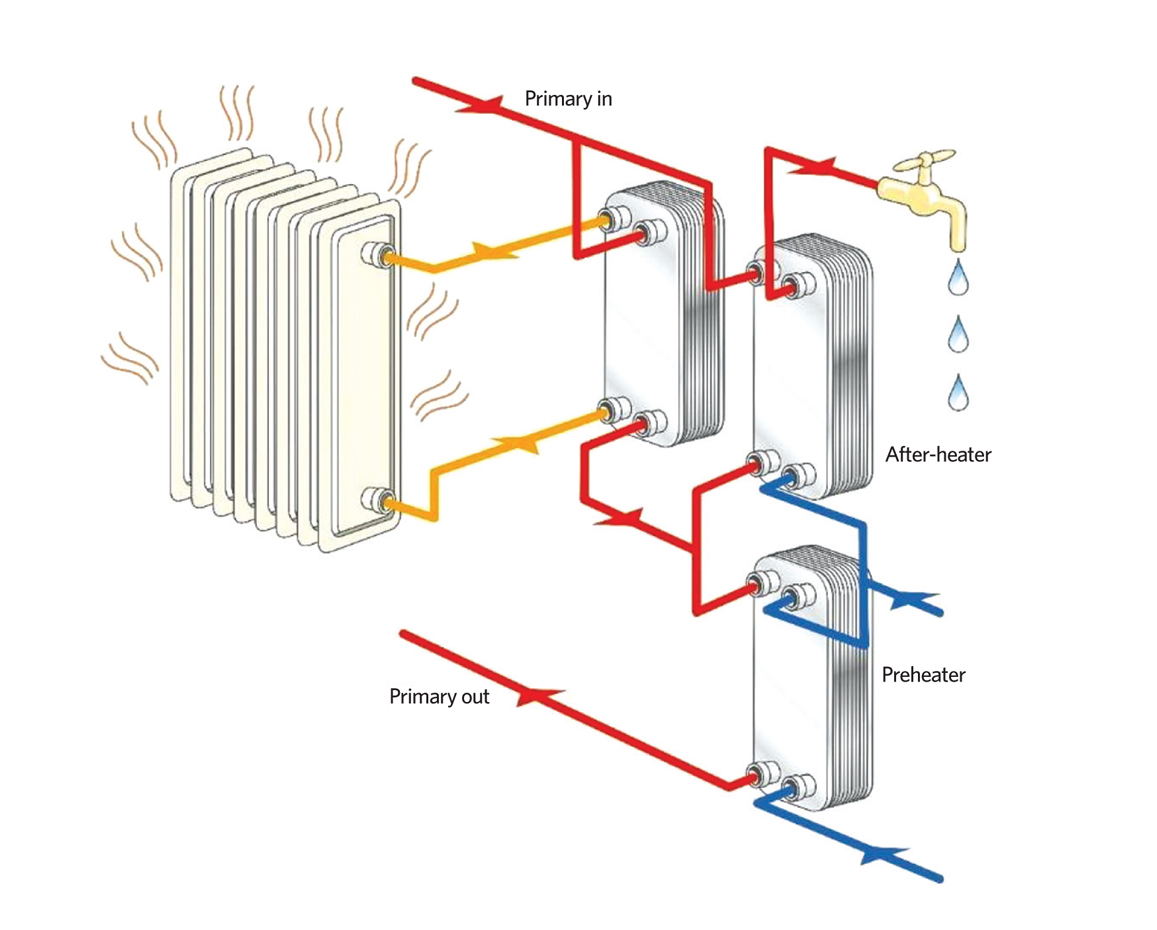
Figure 3: Simplified visualisation of a two-stage connection of consumer systems to the heat network primary flow (Source: Swep)
The proportions of heat used for preheating and final heating are determined in such a way as to make the most efficient use of the heat (exergy). If the building has a significant demand for hot water, this arrangement will typically result in a lower return temperature than would be the case from a parallel connection. The two-stage arrangement may be combined into a single brazed plate heat exchanger, as shown in Figure 4, that would look similar to Figure 5 when installed on site. This would provide the heart of a substation supplying the load for a residential or commercial building – replacing the traditional boiler and calorifier. The November 2017 CIBSE Journal CPD has further details of brazed plate heat exchangers.
The network return water in a typical parallel design is 40°C, whereas simulations and observations have reportedly indicated anything between 40°C and 20°C for a two-stage design – partly depending on heat load, but mostly on how much domestic hot water is being consumed.
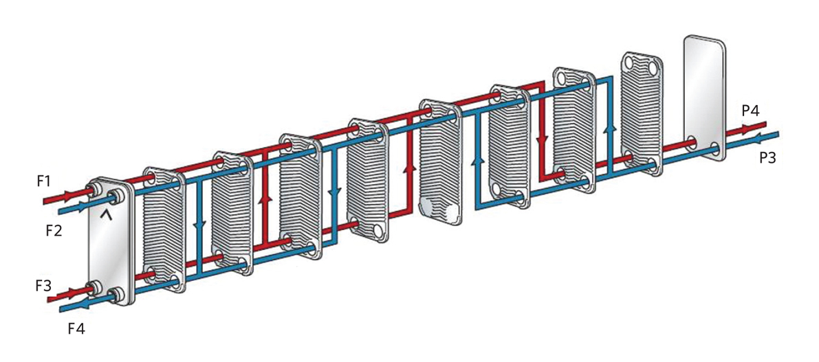
Figure 4: Exploded view of an example two-stage brazed plate heat exchanger (Source: Swep)
Wholesome (mains) cold water enters at P3 and, having been heated, leaves from F4 to pass into the consumer domestic hot-water distribution system. Recirculated domestic hot water, returning from the consumer’s system, enters through F2. Primary water (from the heat network) enters at F3 and F1 (from the consumer radiator/heating circuit) and returns to the heat network through P4.
Example applications
Typical heat network based on a collection of real applications
An example installation based on real applications was modelled4 to determine the comparative performance for parallel and two-stage substations while meeting the same building loads. The results are shown in Table 1.
This indicates an opportunity for significant reductions in return temperatures and flowrates. In this case, a reduction in return temperature of 5K is predicted to also reduce distribution losses by approximately 4%.
Application in Örnsköldsvik, Sweden4
The district heating system in Örnsköldsvik has around 3,000 connected customers. The primary heat is provided by a combined heat and power plant that also produces electricity and industrial steam. For the energy service company (ESCo), as the supplier of district heat, a lower return temperature means that more energy can be recovered in flue gas condensation. This will also reduce the flowrates in the district heating system, and so the pump power and the distribution losses are reduced. The potential impact of a reduced return temperature has been calculated, based on operating data from 2012, and shows that a reduction of the return temperature of 1K represents an annual saving of £76,500. The ambition for the ESCo (Övik Energi) is a flow-to-heat ratio value of 20m3·MWh-1 during the coldest months. To achieve this will mean that the consumers should have an average network temperature differential of 44K. ‘Unnecessary consumption’ describes how much extra water the district heating substations will consume compared with a substation that has reached the company’s target. In this application, a connected sawmill is the customer with the highest unnecessary consumption and is, therefore, also the customer that contributes most to an increase in the return temperature. Had the sawmill reached the temperature differential of 44K, the overall network return temperature would have been reduced by 0.6K.
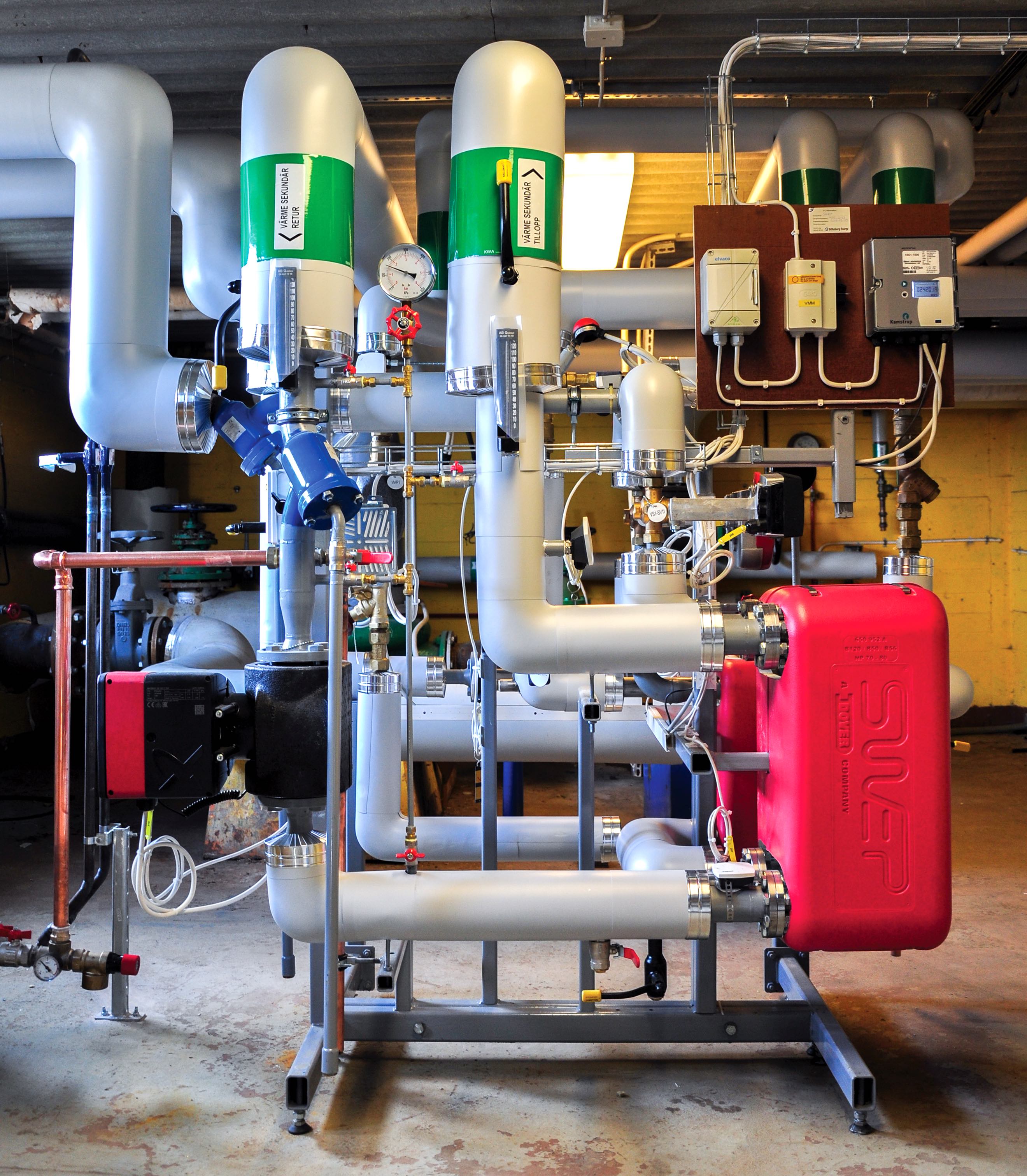
Figure 5: An example of an installed brazed plate heat exchanger (Source: Swep)
However, it is not only the major customers that affect the return temperature. The four small residential substations with the worst performance contribute a 0.2K increase to the return temperature. For the period under investigation, a total of 36 substations had a temperature differential of 20K. If all these 36 had the desired 44K differential, the return temperature would drop by 1.1K, which would deliver an estimated annual saving of around £85,000 per year.
As it is the customers’ substations that determine the return water temperatures, the ESCo is developing a project with its customers to increase the efficiency of the district heating substations. Other measures to improve network performance include investigating the performance and effect of any bypasses in the distribution network, as well as examining the operation and performance of any connected heat sources.
In practice, it is the customers’ facilities that have been identified4 as increasing the return temperature most significantly across a year. Unsurprisingly, investigations show that customer facilities with high energy use and hot water consumption affect the return temperature most. The temperature differential in the network would improve by several degrees if those facilities were to function optimally. For example, if the facility with the highest over-consumption in January had reached a temperature differential of 50K, the overall return temperature could have been reduced by around 2K and delivered increased operational savings.
So the greater temperature differential and reduced return temperature in the district heating system can lead to an increased efficiency in the network and lower costs for the ESCo – and the consumer.
To estimate a return on investment, a project-dependent ‘ball park’ estimate used by a supplier4 indicates that the annual operational saving is in the order of £0.10 per system MWh for each 1K reduction in temperature. To improve utilisation of the heat, consumers may well need encouraging and incentivising to make improvements in their secondary circuits, so that a two-stage system may be successfully employed to deliver low return temperatures.
Consumers typically lack knowledge of how their systems affect the overall efficiency of the network. So, as well as educating them, flow-based fees can be used so that they understand the importance of making improvements.
© Tim Dwyer, 2018.
- With thanks to Christer Frennfelt, Swep, for core technical content.
References:
- London Heat Network Manual, Greater London Authority, 2014.
- District Heating Substations – Design and Installation – Technical regulations F:101, The Swedish District Heating Association, 2008.
- The UK District Energy Association – accessed 15 September 2018.
- Swep internal document.