![]()
In buildings, this reduction can be effected through the evaporation of water, in a similar way as the human body evaporates sweat to maintain body temperature1 as part of the thermoregulatory system. The application of evaporative cooling has been used in and around buildings for millennia – for example, in Iranian (Persian) buildings with integrated evaporative cooling and stack ventilation systems, as shown in Figure 1.
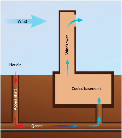
Figure 1: Example of an Iranian building cooled by a qanat and wind tower. Wind passing across the wind tower creates a negative pressure on the leeward side, so drawing air through the system. The evaporative cooling process takes place as the warm dry air passes across the water within the qanat. The cool air flows into the basement of the building, so cooling the building. (Source: Samuel Bailey – commons.wikimedia.org/wiki/File:Qanat_wind_tower.svg)
Evaporating water can give a cooling effect equivalent to its latent heat of evaporation of approximately 2,450kJ·kg-1 at temperatures used in building environmental applications. The heat to evaporate the water – supplying the water with sufficient energy to break the bonds between adjacent molecules – is provided by the sensible heat in the air (that is, flowing adjacent to the wetted surface), so reducing the air dry-bulb temperature. So, for example, by evaporating 1kg of water in an hour (0.28g·s-1) there is potentially a cooling effect of about 2,450kJ·h-1, or approximately 0.68kW, that would be sufficient potentially to sensibly cool 0.050m3·s-1 of air by more than 10K.
The driving force for evaporative cooling is the difference between the actual vapour pressure in the air and the saturated vapour pressure at the water temperature. The process includes both heat and mass transfer. The ‘Lewis number’ (see p20) for water vapour in air is such that, even where the flow is not turbulent, ‘adiabatic’ evaporation may be simply shown as a constant wet-bulb temperature process. In the adiabatic evaporation of water vapour in air, there is no overall change in energy – the process is more fully explained in ASHRAE Fundamentals2 and by Peter Jones.3 This is not only practically useful when describing the process, but also means that it can be readily illustrated on a psychrometric chart, as in Figure 2.
So, the opportunity to evaporatively cool the air can be conveniently expressed in terms of the difference between the air dry-bulb temperature and wet-bulb temperature (known as the ‘wet-bulb depression’). The effectiveness of the evaporative cooler is typically expressed as
η = (θB – θA)/(θA – θwb) where θA and θB are the inlet and outlet air dry-bulb temperatures and θwb is the air wet-bulb temperature. Evaporative systems can be up to 98% effective,4 although commercial evaporative coolers are more likely to be 80% to 90% effective. At the point where the wet-bulb temperature and the dry-bulb temperature are equal (at the adiabatic saturation temperature), there is no opportunity for a net movement of water molecules from a wetted surface into the air and so no further evaporative cooling is possible.
This means that the greatest potential for evaporative cooling is in hot/dry climates. However, the key indicator is the difference between the dry- and wet-bulb temperatures. So, referring to the example summer design temperatures in Table 1, there is likely to be an opportunity for simple evaporative comfort cooling in all these locations (although Hong Kong will have very limited potential).
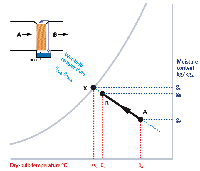
Figure 2: The psychrometric process for evaporative cooling
The two principal applications of evaporative cooling are direct and indirect evaporative cooling. When employing direct evaporative cooling, outdoor air is drawn through a continuously wetted element made of cellulose paper (as shown in Figure 2), plastic or metal, typically available in depths of 50mm to 150mm.
The element can be mounted in a ventilator (Figure 3), with a pump that circulates water from the sump to the distribution system located at the top of the unit, where it is able to flow by gravity, wetting the element and with the excess passing back into the sump, which is automatically supplemented by wholesome water.
As the water evaporates off the medium, the flowing air cools sensibly, while the air moisture content and dewpoint temperature increase so that the air leaving the evaporative cooler will have a high relative humidity. The effectiveness will be influenced by the depth of the medium and the air velocity. The resistance of the cooling medium to airflow will also be determined by the air velocity and the thickness of the material, and can be as low as 20Pa for velocities in the order of 1.5m·s-1, so the required air power requirement is relatively low. This power (watts) can be determined from pressure drop (Pa) x airflow rate (m3·s-1). The other direct operational cost is the wholesome mains water that in the UK costs approximately £2 per m3.
The Lewis Number
Dimensionless values have been empirically established for heat and mass transfer processes.
The Schmidt number, Sc = ν/D, is used when considering diffusion of mass (in this case, water vapour) into a flowing fluid (air) and is the ratio of momentum diffusivity (also known as kinematic viscosity) and mass diffusivity (approximately 0.65 for water diffusion into air at 25°C).
The Prandtl number, Pr = ν/α, indicates how fast the thermal diffusion takes place in comparison to momentum diffusion (approximately 0.73 for air at 25°C).
The Lewis number, Le = α/D, the ratio of thermal diffusivity to mass diffusivity (that is, the rates of thermal propagation to vapour propagation), can be determined from the readily available tabulated values Sc/Pr.
ν is the kinematic viscosity (m2·s-1), which is also known as momentum diffusivity – that is, how well momentum transfers through a fluid (= μ/ρ)
D is the mass diffusivity, of water vapour in air (m2·s-1) – a measure of how quickly water molecules will diffuse into the air. For example, at 25°C this will have a value of approximately 2.4 x 10⁻⁵m2·s-1
μ is the dynamic viscosity of the fluid (Pa·s) – a measure of the shear force required to allow adjacent molecular ‘layers’ to move away from each other; for air at 25°C, this equals 1.84 x 10⁻⁵Pa·s
ρ is the density of the fluid (kg·m-3) – for air at 25°C, this equals
1.18kg·m-3
α is the thermal diffusivity, given by λ/ρCp (m2·s-1) – provides the rate that heat will move through a material; for air at 25°C, this is 2.141 x 10⁻⁵m2·s-1
λ is thermal conductivity (W·m-1·K-1) – for air at 25°C, this equals 2.55 x 10⁻²W·m-1·K-1
Cp is specific heat (J·kg-1·K-1) – for air at 25°C, this equals 1.007 x 10³J·kg-1·K-1
So, for example, at 25°C, the Lewis number can be obtained from α/D = 2.141 x 10⁻⁵/2.4 x 10-5m2·s-1 = 0.9, or from Sc/Pr = 0.65/0.73 = 0.9
The cooled, high percentage saturation air can then be directly introduced into the occupied space through a ventilation unit (such as in the one in Figure 4). In this case, the supplied cooled fresh air mixes with the room air, moderating the room air dry-bulb temperature and increasing the room air moisture content.
The introduction of the high humidity air from the evaporative cooler will tend to increase the space humidity. Fortunately, in terms of human comfort, high relative humidity can still be acceptable as long as the dry-bulb temperature is within a reasonable range. CIBSE Guide A5 indicates that 70% saturation is acceptable. When calculating the predicted mean vote (PMV) for comfort, a higher humidity has a modest effect, and BS EN ISO77306 suggests that a 10% increase in humidity is felt to be as warm as a 0.3K rise in the operative (comfort) temperature. (At higher temperatures and activities, the influence is greater.)
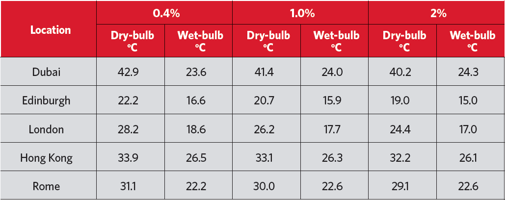
Table 1: Cooling design conditions for a selection of locations (Source: CIBSE Guide A 2015, Chapter 2 appendices)
When using wet surfaces in ventilation systems, risks from mould, bacteria and – specifically – legionella are always a concern. BSRIA7 notes that to avoid a buildup of solids in the sump, some or all of the circulating water should be periodically drawn off and replaced with fresh water. The low water temperature in the sump is unlikely to propagate bacteria; however, if they do become established, they are very unlikely to be transferred into the air stream – as long as the air velocity remains below the point at which aerosols are generated.
Where it is important that the space humidity is not increased, or possibly where less wholesome water is available to supply the evaporative cooling, an indirect evaporative cooler may be used. This type of system (as discussed in the CIBSE Journal CPD in March 2017) will provide drier cool air but will consume much more water, be more complex, larger and heavier, and demand more fan power. There are more complex further enhancements (such as the Maisotsenko cycle, as discussed by Hammond in the March 2018 CIBSE Journal) that can extend the operating range and effectiveness of evaporative cooling devices.
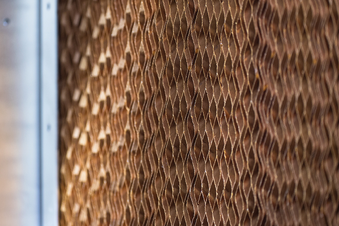
Figure 3: The surface of an example cellulose paper evaporative cooling panel – often referred to as a ‘pad’ (Source: Colt)
When using simple ventilators with integrated direct – or indirect – evaporative coolers to supply the cooled outdoor air, the warmer, more humid, vitiated air needs to be removed from the space. This would typically be removed at high level by means of natural ventilators or, where this is not possible, using exhaust fans.
The ventilators supply outdoor air and are typically available with heating elements for tempering the supply air temperatures when cooling is not required. During colder periods, where freezing outside conditions would be expected, the evaporative coolers would not be used, and would have been drained down and isolated as part of a winterisation process.
Where higher-humidity indoor air is unacceptable, it may be better to use an indirect method of evaporative cooling.
There will be a limit to the amount of cooling that may be supplied in simple direct or indirect evaporative systems and, of course, these systems cannot provide any dehumidification. Proper access and maintenance are important to ensure that any filtration is in good order and that the evaporative media and water distribution system are kept in a healthy state.
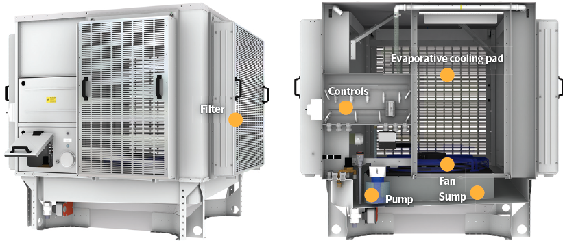
Figure 4: Section view of evaporative cooling ventilation unit (Source: Colt)
There are significant benefits in the simplicity of the systems, making them less costly to install and operate compared with full air conditioning, but at a more limited capability. Since the working fluid is water, it avoids the handling – and environmental concerns – of more complex chemical refrigerants. As the external temperature increases, so does the potential cooling effect, which contrasts with a traditional vapour compression refrigeration system in which the performance drops with increasing outside temperature. Practically, most European and non-tropical locations are worthy of investigation for evaporative cooling technology.
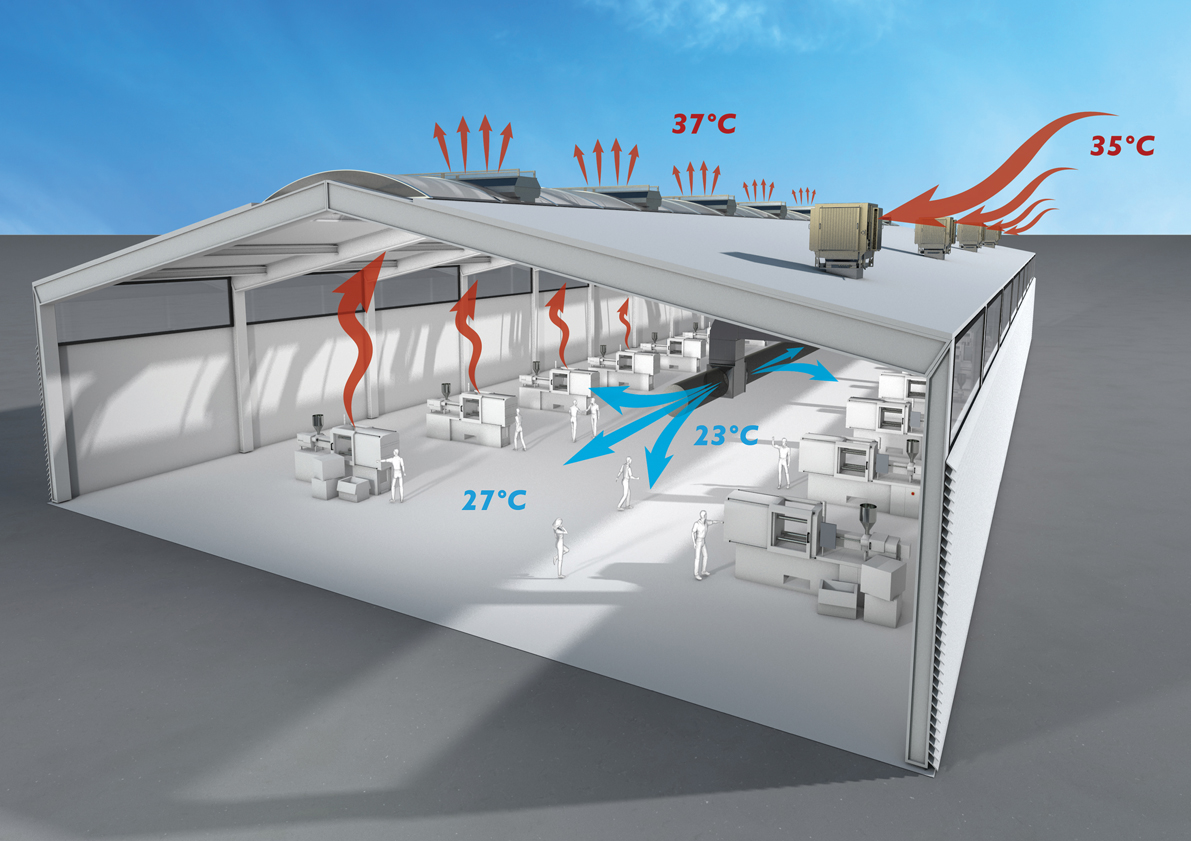
Figure 5: An example application (showing dry-bulb temperatures) of applying high-level direct evaporative ventilation units (Source: Colt)
Psychrometric chart
For a refresher on the application of the psychrometric chart and the associated air processes, see the CPD modules 3, 7 and 9 at www.cibsejournal.com/cpd/year/2009/
© Tim Dwyer, 2018.
References
- Havenith, G et al, Evaporative cooling: effective latent heat of evaporation in relation to evaporation distance from the skin, J Appl Physiol 114: 778–785, 2013.
- ASHRAE Fundamentals 2017 Handbook, pp 6.9-6.10, ASHRAE 2017.
- Jones, WP, Air Conditioning Engineering, Section 3, Routledge, 2000.
- 2016 ASHRAE Handbook – HVAC Systems and Equipment, Chapter 8 Section 4.
- CIBSE Guide A, Environmental design, Sect. 1.3.1.3, CIBSE 2015.
- BS EN ISO 7730:2005 Ergonomics of the thermal environment Analytical determination and interpretation of thermal comfort using calculation of the PMV and PPD indices and local thermal comfort criteria, BSI 2005.
- BSRIA BG 8/2004 Free cooling systems, BSRIA 2004.