
This CPD will draw and build on previous CPD articles in CIBSE Journal to consider the application of continuous flow hot-water systems, such as those in Figure 1.
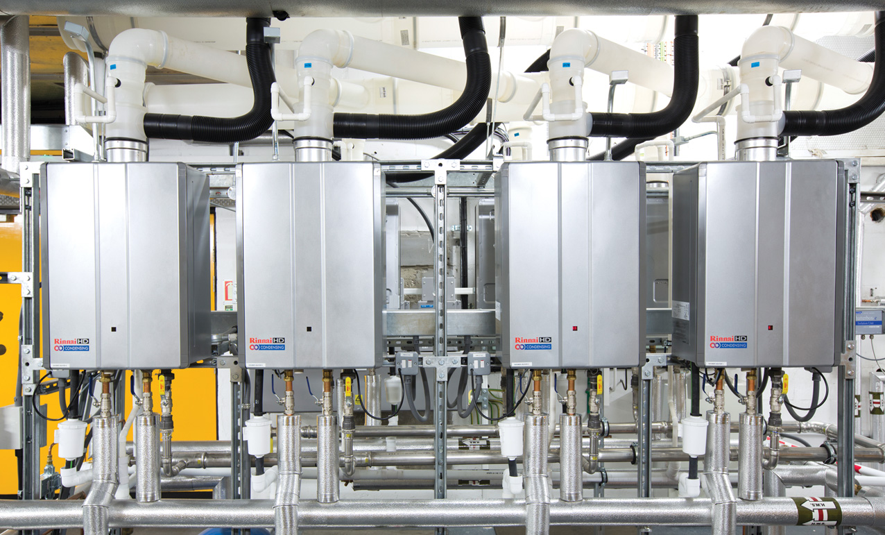
Figure 1: Example of a continuous flow cascade system, as installed in an institutional building (Source: Rinnai UK)
As consumer demand becomes less uniform, the sizing of DHW systems that rely on storage to overcome the inability to meet peak demand is an increasingly challenging engineering task. The significant difference in using continuous flow gas water heaters (as described in the panel) is that – in their simplest form – there is no storage and the system will be designed to instantaneously meet peak hot-water loads. When drawing on mains water, continuous direct-fired hot-water heaters (such as that shown in Figure 2) are able to consistently operate in condensing mode. The low-temperature incoming mains water is well below the flue gas condensing temperature (around 57°C), so the heat exchangers in the unit can fully condense the water vapour in the products of combustion when taking water directly from the mains supply, which is typically below 10°C. The close control integrated into such systems is able to deliver a continuous flow of hot water at a set point temperature to ±1K.
Legionella control
The UK Health and Safety Executive (HSE) advises1 that the primary method used to control the risk from legionella is water temperature control. Where there are hot-water storage cylinders (calorifiers), water should be stored at 60°C or higher and distribution should be at 50°C (with local mixing at outlets to provide appropriate water temperatures). For continuous flow hot-water heating systems, there is inherently no storage and so no need to heat up a volume of storage water to reduce legionella risk, as the cold-water feed to the heaters is direct from the wholesome main supply.
However, regardless of whether the hot water is provided by a continuous flow water heater, in larger systems where there is a need for recirculation pipework (as illustrated in Figure 3), there is inherently increased system water volume and opportunities for ‘dead-legs’. The controls for continuous flow water systems can be programmed to circulate water at 60°C (or above) when the building is unoccupied (for example, at weekends or at night) to supply thermal disinfection for legionella control in the distribution pipework. By the time of reoccupation, the temperature will be reduced to normal operating temperatures.
The hot-water system – particularly rarely used shower heads or terminal fittings – will still require regular checking and disinfection.
The operation of a continuous flow gas hot-water heater
When the flowrate drawn by the hot-water system is sufficient (as sensed by the water-flow sensor) the main controller will initiate the ignition sequence. The fan then purges air through the combustion chamber and the flue (and the airflow is confirmed). A spark is established and the main and intermediate gas valves open. The resulting combustion is proved by the flame rod and the spark shuts down. The main controller constantly monitors the outlet water temperature, the temperature set point, and the volume of water passing through, and from these it can assess the heat requirement and modulate the three gas valves accordingly. The outgoing temperature sensor provides a signal at 150 times a second to ensure that the temperature can be closely controlled. If the demand on the system is too great for the heater to maintain temperature a water-flow control valve will operate to ensure the correct outgoing temperature is maintained.
There is no storage of water in the heater, and as soon as the demand for hot water changes or stops, the water heater will modulate – or halt – its output to suit. When there is no demand for hot water, the heater returns to standby, with the gas-control valve closed and the water-flow control valve reset to standby position, and freeze protection is activated as needed.

Figure 2: The functional components of a continuous flow gas hot-water heater (Source: Rinnai UK)
Reduction and prevention of limescale
The UK Carbon Trust considers2 that for each 1mm layer of limescale on the heat transfer surfaces there will be a 7% increase in energy input to the boiler to meet the same heat demand. Limescale will also give increased opportunity for the accumulation and growth of bacteria such as legionella. To maintain efficiency in continuous flow water heaters that draw untreated cold water direct from the mains, water treatment may be needed in areas that have hardness exceeding 150mg·L-1 of calcium carbonate (CaCO3). As the water that is being directly heated by the hot-water heater must maintain its wholesome nature, bulk chemical dosing is not appropriate. However, an electrolytic method can be successfully employed that uses a zinc sacrificial anode, enclosed in an inline cylindrical housing, which is incorporated in the incoming water supply (as shown in the dotted section of Figure 3). This doses the water with trace amounts of zinc (a few parts per billion) sufficient to alter the structure of any precipitating limescale from calcite to the much more soluble aragonite. The change in the shape of crystals reduces the adherence to surfaces as scale.
These systems are simple to install and require little space, they have practically no maintenance requirements and – having no need for salt or regeneration water – make the systems significantly cheaper to operate compared with other water-softening methods.

Figure 3: Continuous flow gas DHW system with recirculation and optional electrolytic water treatment (dependent on local water hardness) (Source: Rinnai UK)
Integrating continuous flow hot-water heaters with renewable heat sources
The integration of continuous flow hot-water systems with thermal stores of wholesome water can offer a closely controlled supply of hot water that can instantly increase the flow temperature of the stored water as required to meet the distribution needs. When the store is able to directly meet the required temperature, the hot-water heater will not fire.
So, for example, in Figure 4, if the stored water is at the required distribution set point because of the heat collected by the solar panels, when hot water is drawn off, the water from the store passes through the heater without it firing. If the cylinder is at a lower temperature, then the continuous flow water heater will fire to provide the required supply temperature (and will be limited to a maximum safe temperature) to meet the hot-water heating requirements, while optimising gas usage and maximising solar gains.
This thermal store can, of course, link in with other renewable heat sources.
Performance modelling
As detailed in the October 2016 and September 2017 CPD articles, modelling of example applications (undertaken by an independent third party) compared the lifetime benefit of operating continuous flow hot-water systems with that of more traditional options.
Different heating and hot-water supply scenarios were examined3 for two student accommodation blocks, with a total of 643 occupants, to give comparative 20-year net present value (NPV) costs and equivalent carbon emissions, based on standard UK daily DHW usage data.4
Six systems variants were compared, including three with no storage of DHW:
- Gas boiler LTHW heating + gas continuous flow DHW
- Electric space heating + gas continuous flow DHW
- Air-source heat pump (ASHP) heating + gas continuous flow DHW.
Three included domestic hot water storage:
- Gas boiler LTHW heating + insulated storage calorifier (this was the base system)
- Electric space heating + electric DHW insulated storage calorifier
- ASHP heating + ASHP DHW + insulated storage calorifier.

Figure 4: Simplified schematic of a solar thermal collector and associated thermal store with continuous flow hot-water system (Source: Rinnai)
The demand for space heating was determined using a dynamic thermal model for a building that met current regulatory requirements, and applied the CIBSE Test Reference Year for London (TRY)5 to the two student accommodation blocks. The base system – a modular gas boiler system, which was based on six modules each supplying 240kW, with a primary flow of 80°C and return of 50°C – can meet 37% of the hourly peak DHW load and work together with two 2,900L DHW calorifiers storing water at 65°C, with approximately 15kWh daily standing losses.
The insulated recirculating DHW distribution circuit was modelled as returning water at 55°C, and the heat loss from the pipework was seasonally adjusted for both water and ambient temperatures.
The analysis applied projected retail fuel costs and equivalent carbon emissions factors for electricity and gas, based on UK government data.6
Figure 5 illustrates the NPV comparison on capital and operational costs, which – in this particular case – indicates that the systems need to be considered for at least five to 10 years before the life-cycle trend is clearly set.
On a smaller scale, an example was modelled7 for a shower block in a holiday camp, with six showers and four basin taps, to establish the comparative performance of a continuous flow hot-water system with those of both a direct-fired storage option and a more traditional condensing gas boiler with storage cylinder.

Figure 5: Zero to 20-year NPV of the base case, and five options based on a discount rate of 3.5% and an inflation rate of 2% for maintenance costs (Source: Aecom/Rinnai Research Report7)
The continuous flow system was based on four heavy-duty water heaters, each with a nominal output of 48kW – equating to around 14L per minute of hot water at 50K temperature rise (from 10°C to 60°C) and a gross thermal efficiency of 95%. The indirect-fired storage option was based on a pair of 40kW condensing natural gas boilers with a gross efficiency of 89%, heating a pair of 400L cylinders. The direct-fired storage option consisted of a pair of 230L cylinders with integral burners, each with around 37kW output and gross thermal efficiency assumed as 96%.
The model indicated that, in this scenario, the continuous flow system has the lowest 20-year NPV – 6% to 7% lower than the two storage systems.
A further analysis was undertaken for the increasingly common application of a fast-food restaurant. Echoing common trends, the boiler used for the indirect-fired storage system was assumed to serve only the hot-water cylinder, as fast-food restaurants typically use heat pump systems to provide space conditioning. Using similar standard operational and efficiency assumptions as that of the previous example, the resulting NPVs again indicated that fuel consumption of the continuous flow system is around 6% to 7% lower than the two example storage systems, based on that 20-year analysis period.
Monitoring the performance of continuous flow hot-water heaters
The operation of such systems can be readily monitored through custom gateways feeding the operational state to building management systems (BMS) networks. This can allow remote access to live operational data from the water heaters, which can be used for data capture (for example, flowrates and delivery temperatures) and to trigger appropriate planned maintenance or signal the need for servicing if any appliance suffers from a fault.
© Tim Dwyer, 2018.