![]()
The influence of the radiant environment on occupants
The operative temperature, θc (°C) – a standard measure of human thermal comfort – is calculated1 from θc = where θai is the air dry-bulb
temperature (°C), θr is the mean radiant temperature (°C) and v is the mean air speed (m·s-1).
In cases where the air is outside the influence of significant motive forces (such as fans, diffusers and natural ventilation inlets), the air speed is taken as being of a similar magnitude to that of natural convection (≈0.1m·s-1). So, the calculation for operative temperature is typically simplified to θc = 0.5·θai + 0.5·θr. Therefore, within limits, the balance of thermal comfort is determined by the average of the air dry-bulb temperature and the mean radiant temperature.
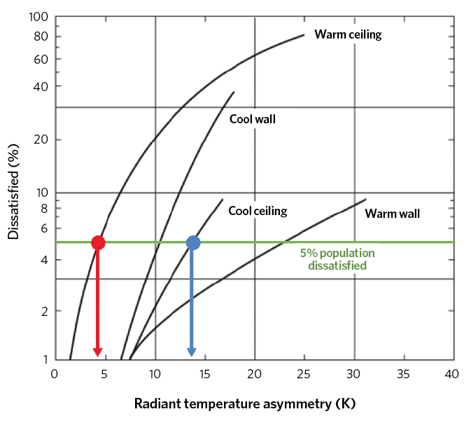
Figure 1: Percentage dissatisfied due to asymmetric radiation only, based on work by Ole Fanger (Source: CIBSE Guide A 2016 Fig 1.11)
As discussed in some detail in Section 1.6 of CIBSE Guide A1, there are several other factors that should be considered when assessing the overall thermal comfort of occupants. However, the practical impact that is explicitly related to radiant heat transfer is due to the asymmetry of the radiant surfaces and their temperature. As shown in Figure 1, the influence of surface temperatures on comfort has been shown to be highly dependent on their relative position to the occupant. So, for example, to meet a ‘percentage of population dissatisfied’ (PPD) figure of 5% would indicate that, for human comfort, the average ceiling temperature should be no cooler than around 14K less than the room air temperature, and should be no warmer than around 4K. (This is approximately reflected in ISO77302 for category A and B buildings.)
The actual impact of radiation will be determined not only by the surface temperature, but also by the view (or shape) factor – that is, the amount that the surface impacts on the occupant. This can be geometrically complex to determine and, as occupants move around or are positioned differently within a space, will vary across the room. The mean radiant temperature, θr, is used to assess the average radiant temperature at any particular point, accounting for the temperatures, positions, radiant properties and areas of all the surrounding surfaces. It has been practically indirectly assessed through the use of a globe thermometer in a single position (experimentally, often suspended in the centre of a room) but – as confirmed by Alfano et al3 – measuring it swiftly is challenging. The impact of all the non-uniform surface temperatures and shapes will integrate with other factors to give the sensation of comfort and wellbeing, so the impact of radiant heat exchange is likely to vary across the space – making it particularly difficult to determine a representative value. The CBE Comfort Tool at http://comfort.cbe.berkeley.edu/ offers a simple device to predict the effect of asymmetric radiation on comfort – select the EN 15251 tab and the ‘Local discomfort’ button.
Cooling and heating with radiant sails
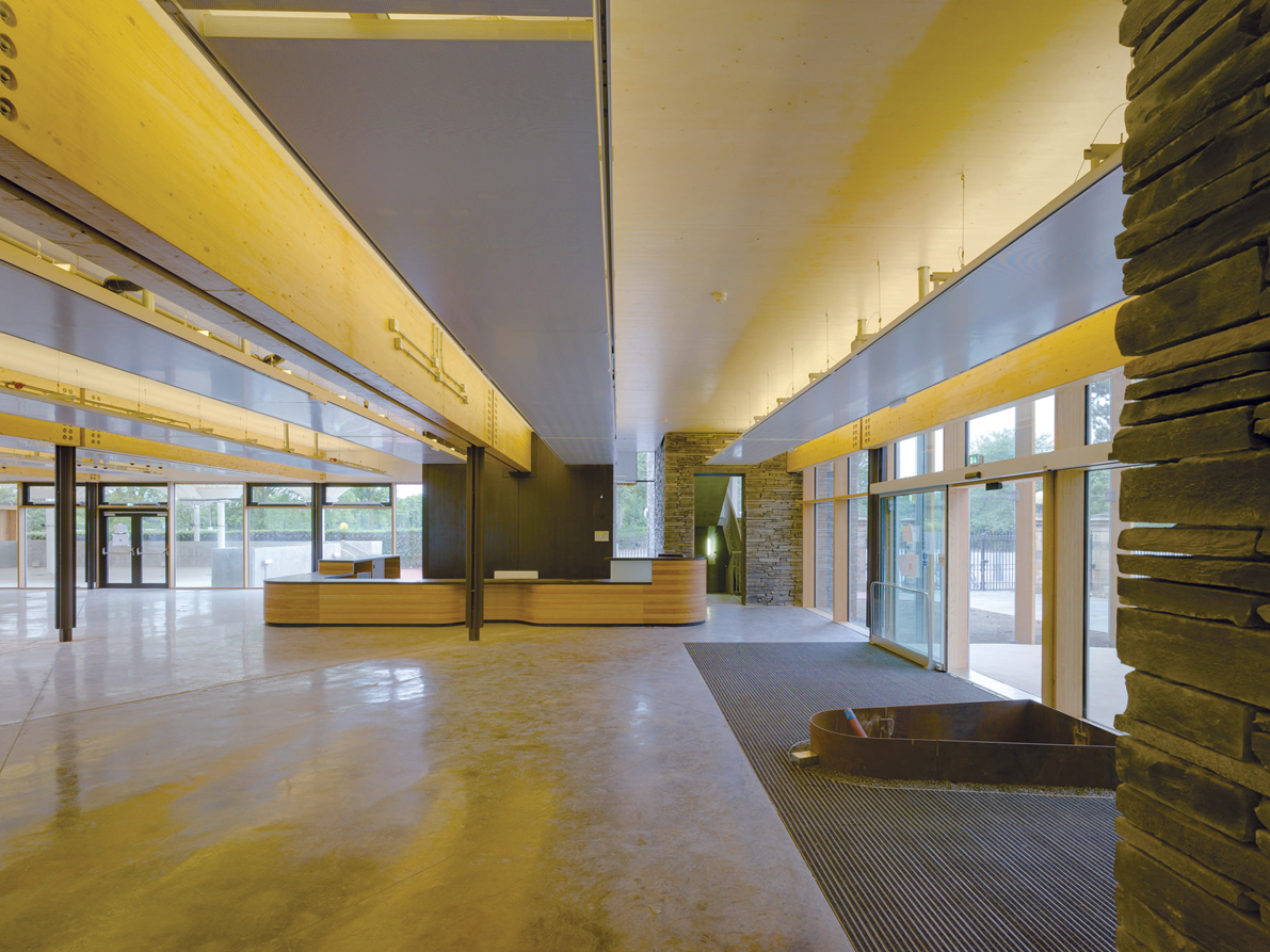
Figure 2: Suspended radiant sails integrated into the ceiling design in the Royal Botanic Garden, Edinburgh (Source: Zehnder)
Aside from the fixings, the radiant sail is designed so it has no significant physical (or thermal) connection to the structural soffit, and a space is maintained between the panel and the surface above it (as shown in the installation in Figure 2). Radiant sails may be used for heating or cooling (simply depending on the relative temperature of water flowing through the coils) and the performance of both modes is assessed by methods as described in BS EN 140374 and BS EN 14240.5 The resulting thermal output is given in terms of K·Δθn, where K and n have been found by undertaking standard tests on the panel, and Δθ is the difference between the average sail temperature and the room. By virtue of using water to convey heating and cooling into the space, as opposed to using an all-air system, energy distribution costs and space requirements are reduced and – as demonstrated by Kosonen et al6 – for properly sized and installed systems, the levels of comfort delivered by radiant and convective systems are practically the same. The sail will not be wholly radiative, as the surface will cool, or heat, adjacent air all around the sail. Cooled air will then convect downwards at a relatively low air velocity and, when heating, the warmed air will move upwards, as a result of convective forces.
When in cooling mode, the surfaces of a radiant sail must remain above the room air dew-point temperature to prevent surface condensation. This is often done by sensing the temperature on the pipe supplying the radiant panel and employing a mixing circuit to control the water temperature. Where the absolute moisture content in the room is high (and so the air dew-point temperature is also high) the cooling performance will be limited, as the sail must operate with warmer cooling water. If the room air moisture content is likely to be particularly high – possibly because of latent gains from people or processes – a radiant cooling system will typically be operated in conjunction with a dehumidifying ventilation system.
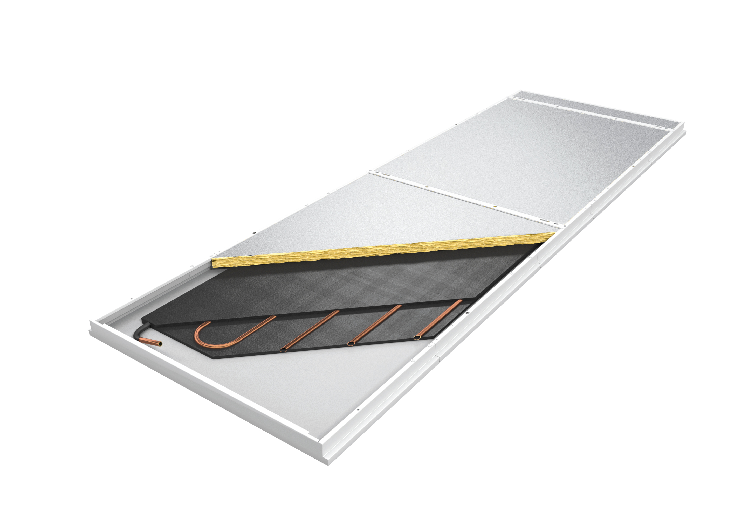
Figure 3: A cutaway showing the upper surface of a sail that includes graphite sheets, employed to improve the consistency of the panel surface temperature (Source: Zehnder)
As the surface should not drop below the air dew-point temperature, an application in a location such as the UK would practically mean that the chilled water flow is likely to operate at temperatures between 14°C and 18°C. (For comparison, the dew-point temperature of air with 26°C dry-bulb temperature and 60% saturation is 18°C, as would be a typical indoor maximum design condition.)
An example steel commercial sail (600mm x 2400mm) has a K of 13.5 and an index n of 1.06 so with, say, an 8K difference in temperature between the sail and the room, the cooling potential (0.6m x 2.4m) x 13.5 x 81.06 = 176W (or approximately 120W·m-2). This output can be improved significantly with panels that incorporate enhanced heat transfer materials (such as that in Figure 3) to give a more even temperature across the whole sail surface, as shown in Figure 4.
With the cooling medium being at temperatures typically greater than 14°C, opportunities open up to use efficient heat pump/refrigeration systems or, potentially, passive or evaporative cooling.
The sails can also be used for heating, by passing relatively hot water through the coil. Despite some convection from the surfaces, the sails are a predominantly radiant heater with a large heat transfer surface. The impact of using a largely radiant heater can be examined by inspecting the CIBSE Simple Method7, where the average total room heat loss Φt (W) is given by
Φt = [F1cuΣ(AU) + F2cuCV] (θc – θao)
where F1cu and F2cu are factors that are related to the type of heat source, Σ(AU) is the sum of the products of the surface area and corresponding U value for each surface where there is a heat flow (W·K-1), CV is the ventilation coefficient (W·K-1), θc is the mean operative temperature in the centre of the room (°C),and θao is the outside air temperature (°C).
The factors F1cu and F2cu are obtained from
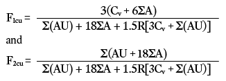
where Σ(A) is the total area through which heat flows (m2), and R is the radiant fraction of the heat source. This will have high value for radiant heat sources (with a maximum value of 1 for a pure radiant source) and a low value for predominantly convective sources (practically zero for ventilation systems). As the value of R increases, both factors F1cu and F2cu will reduce, so the resulting average heat loss, Φt, will reduce. The increase in the radiant temperature of the air within a space will be reflected in reduced energy use, predominantly because of reduction in the temperature of ventilation air supply, and can be particularly beneficial in intermittently heated spaces where the volume of the space is large, as the bulk air volume requires less heating during times of discontinuous occupation.
Controlling radiant sails
The thermal inertia of the panels is small, so providing short response times. This means that they can be particularly useful where the load is likely to vary, but can make it challenging to monitor the space conditions reliably. In an attempt to interpret practically the operative temperature in a space, black bulb or radiant temperature sensors are used (such as that in Figure 5). Where standard air temperature sensors are used, with a predominantly radiant system, an attempt to simulate the radiant effect is made by resetting the set-point by 3K for heating and 2K for cooling.8
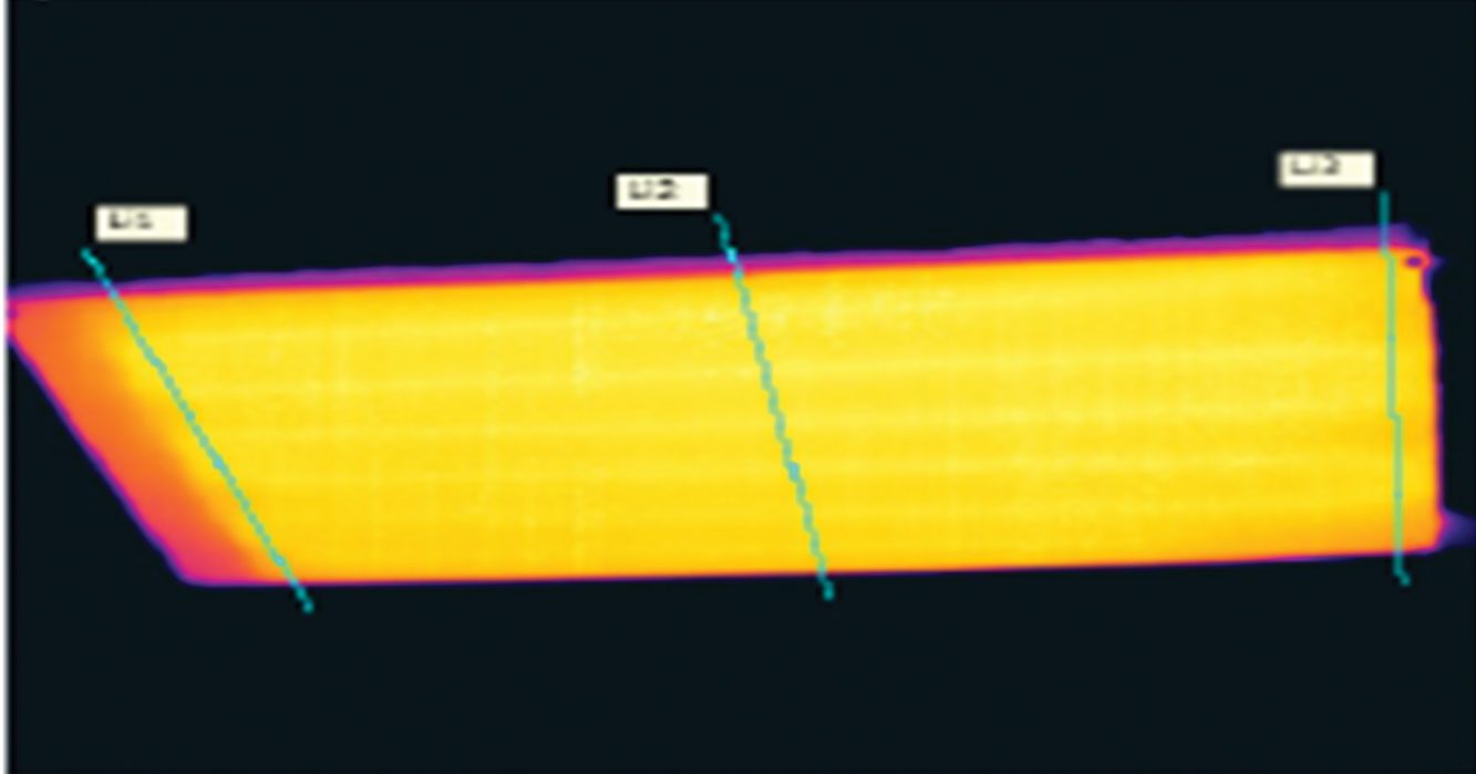
Figure 4: Thermographic image of a sail with enhanced coil-to-panel heat transfer, with a consistent surface temperature that can increase the effective output compared with more basic constructions (Source: Zehnder)
When using the sails with a single coil for heating and cooling, there are a number of ways to arrange the system. A two-pipe changeover system (for heating and cooling) is not typically recommended, as demand for heating and cooling may well be different across a building. Three-pipe and four-pipe arrangements allow concurrent heating and cooling – the four-pipe system is preferred, as it offers more useful return water temperatures and simpler control.
As well as controlling the required room temperature, a dew-point sensor must protect against moisture damage. This will influence the chilled water temperature being supplied to the zone to maintain the surface temperature above the room air dew-point temperature.
It is possible to put separate heating and cooling coils on the sail. As well as simplifying the control (by having two completely separate circuits), this allows – for example – for higher temperature heating systems that require a smaller coil area or cooling systems that include some specific water treatment.
Application of radiant sails
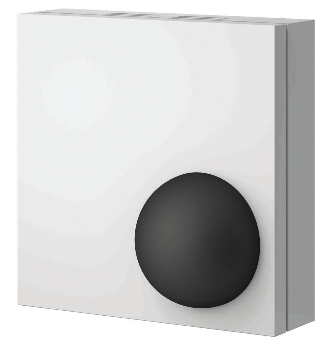
Figure 5: A black bulb temperature sensor (Source: Zehnder)
The sails can be combined with architectural lighting as part of an integrated scheme, and can be fabricated with perforations to affect the acoustic performance of the space, as shown in Figure 6.
Flexibility in the building space can be accommodated, as ceiling sails can be located appropriately to supply the required conditioning based on ‘active’ areas within a building, such as where more people are located. As the sails are suspended, they can provide a source of both hydronic heating and cooling without taking up floor area.
There are several areas in which the proper application of a radiant sail system may contribute to the accumulation of Breeam environmental points, for example through:
- System zoning
- Reduced noise levels when using perforated panels that reduce the reflection and increase the absorption of sound
- Potentially reduced size of cooling plant (this requires less than 5kg of refrigerant sealed within the unit, such as a medium-sized commercial heat pump)
Basic radiant panels are relatively simple pieces of equipment, with no moving parts. Some manufacturers include a microbial finish to prevent the growth of micro-organisms and, together with the simple easy-clean construction, this means that little maintenance is required. Radiant sails are manufactured from a combination of steel, aluminium or copper and, typically, are
fully recyclable.
In appropriate applications, the operational energy consumption is likely to be reduced (compared with convective and slow-response systems) as a result of a combination of the more moderate temperatures of cooling and heating enabled by large heat transfer surfaces, the fast response of the system and the reduced air temperature – while still maintaining appropriate operative temperatures.
© Tim Dwyer, 2018.
References:
- CIBSE Guide A, Chapter 1, CIBSE 2016.
- BS EN ISO 7730, Ergonomics of the thermal environment – Analytical determination and interpretation of thermal comfort using calculation of the PMV and PPD indices and local thermal comfort criteria, 2005.
- Alfano, F R A et al, ‘On the measurement of the mean radiant temperature and its influence on the indoor thermal environment assessment’, Building and Environment 63 pp79-88, 2013.
- BS EN 14037 Free hanging heating and cooling surfaces for water with a temperature below 120°C, BSI 2016.
- BS EN 14240 Ventilation for buildings – Chilled ceilings – Testing and rating, BSI 2004.
- Kosonen, R et al, ‘Thermal comfort with radiant and convective cooling systems’, REHVA Journal, June 2014.
- CIBSE Guide A, Appendix 5.A2, CIBSE 2016.
- Zehnder Radiant Cooling CIBSE-recognised CPD, 2018.