![]()
BPHEs were originally developed to allow high operational pressures and temperatures, but are now commonly applied across numerous applications. Typically, in building systems they will be used to transfer heat between primary and secondary water (or glycol) systems. They are available in a range of sizes, capable of transferring from only a few kilowatts up to several megawatts, and by virtue of their relatively small dimensions have enabled the development of products and applications that would have hitherto been less practical or even impossible.
Brazed plate heat exchangers are normally manufactured from pressed, stainless steel plates sandwiched, and brazed, together to form a compact heat transfer device. The manufacturing process presses the thin steel plates together with a copper foil, creating a plate embossed with a ‘herringbone’ type pattern. The pattern’s orientation is alternated for each successive plate, creating a ‘package’ of plates with channels through which the fluid can flow. The end plate in the package is either plain or has four holes to allow the connection of pipework for the two fluid streams. (Examples of packages are shown in Figure 1.)
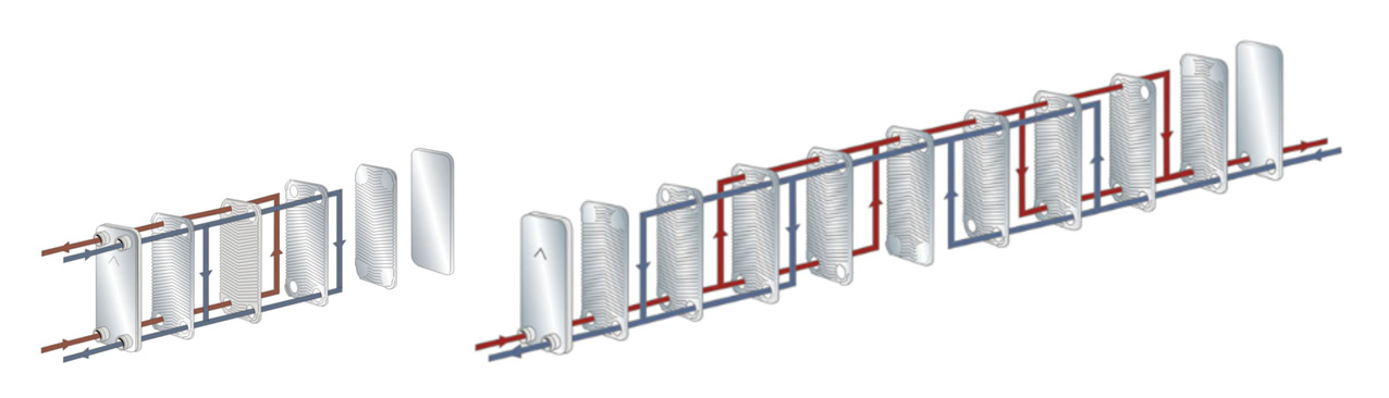
Figure 1: Examples of flow configurations of BPHEs – single pass and multi-pass (Source: SWEP)
After the packages of plates have been gathered, they are stacked in batches and placed in a furnace where they are heated in a partial vacuum. A brazed joint is formed at every contact point between the channel plates (where the copper has melted). Copper is the standard brazing material used in BPHEs and applied across a wide range of sizes and models. Copper has a melting point of 1,083°C and a normal maximum operating temperature of 225°C. Nickel, with a melting point of 1,453°C, can be used for specialist applications requiring higher temperatures and fluids aggressive to copper, with a maximum operating temperature of 350°C.
Following brazing, the units are tested for leaks, using inert gas, ensuring that there is no external or internal leakage. They are pressure-tested typically at a pressure 50% higher than the normal maximum operating pressure.
BPHE operation
The operating principle of a BPHE is based on the simple transfer of heat energy from the warmer media to the cooler one. The secondary side always has one more flow channel than the primary side – provided by the first and last channels – and contains the secondary fluid surrounding the primary channel. The secondary circuit also has a lower pressure drop because it contains one more (parallel) channel.
The flow arrangement can be either counter flow or parallel flow (Figure 2).
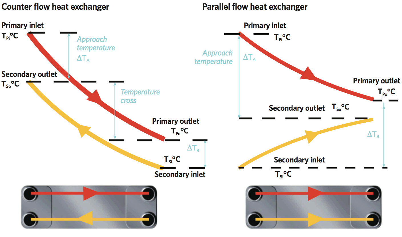
Figure 2: Temperature profiles for counter flow and parallel flow BPHE
Counter flow is preferred, since it enables a closer approach temperature (this is the temperature difference between the inlet of the primary and the outlet of the secondary flows), as well as a greater total heat exchange. As with any heat exchanger, the heat transfer from one flow to the other through a BPHE can be determined from U A ΔTLM, where U is the average thermal transmittance from one flow to the other (W·m-2·K-1); A is the overall heat transfer area (m2); and ΔTLM is the log mean temperature difference between the two flows.
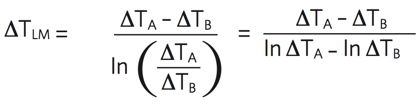
ΔTLM – often referred to as LMTD – is determined from the entering and leaving primary and secondary temperatures:
So, for example, referring to the recommended system temperatures in Table 2 of COP1 Heat networks: Code of Practice for the UK,1 considering a (secondary side) radiator system that has a flow temperature of 70°C and a return of 40°C, supplied through a counter flow BPHE from a heat network (primary side) with a flow temperature of 80°C and a return of 44°C:
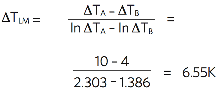
A small change in the primary or secondary flow temperatures can make a substantial difference to ΔTLM, and so can have a significant effect on the sizing of the BPHE. In the previous example, if the primary flow temperature is increased by 2K, then ΔTLM will increase by 11%.
The overall sensible (single-phase) heat transfer in kW can also be determined from m·Cp·ΔT, where m is the mass flow rate (kg·s-1) of either one of the flows (most usefully, the secondary flow), Cp is the specific heat capacity (kJ·kg-1·K-1) of the flowing liquid, and ΔT is the difference between the inlet and outlet temperatures for that flow (K).
The thermal transmittance, U, is a function of the thermal resistance of the plate material, the surface heat transfer coefficient on both sides of the plates, and an allowance for ‘fouling’. The thin – circa 0.4mm – stainless steel plates have a very low thermal resistance and, because of the turbulent flow through the heat exchanger, there is very little deposition and accumulation of unwanted materials – such as scale, algae, suspended solids and insoluble salts – on the surfaces, so fouling factors are low. The surface heat transfers are dependent on the fluid characteristics and the flow, and so are set by the application. Turbulence creates increased heat transfer and reduces the boundary layer thickness but at a higher pressure drop, and so with greater pumping costs.
The basic performance of the heat exchanger is determined by the patterns in the plates and the channel sizes in the BPHE. This is characterised by the so called ‘theta value’ of the plates, used by manufacturers to represent the ‘number of transfer units’ (NTU) given (for a particular flow) by 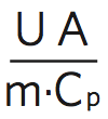
The NTU method is used to predict outlet temperatures of heat exchangers using simple calculations, and does not require a knowledge of the log mean temperature difference as this would not necessarily be known. A high theta value would be 3 or above and a low theta would be close to 1.

Figure 3: Examples of high, low and medium theta plate configurations. From left to right: high theta, low theta and medium theta – where a high theta plate faces a low theta plate
Using high theta plates will provide ‘high thermal length’, so offering very effective heat exchangers. The thermal length of a particular flow channel is a function of the channel hydraulic diameter, plate length, and the angle of the corrugations, along with the physical properties of the flowing fluids. Increased turbulence will also reduce fouling.
The choice and configuration of plates will allow the BPHE to provide the required heat exchange characteristic and so deliver the desired secondary outlet temperature. The examples in Figure 4 give an indication of the exchanges from three arrangements with the same primary and secondary input temperatures.
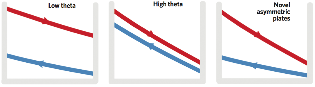
Figure 4: Indicative examples of the temperature profiles that would typically be delivered using low and high theta, and novel asymmetrical design plates
High theta plates typically have a highly angled chevron pattern, whereas low theta plates typically have less acute angles. A mixture of patterns is used when an intermediate thermal effectiveness is required. Manufacturers have developed novel arrangements, such as an asymmetrical design, that has an improved heat transfer, so increasing the system’s thermal performance. It also has a lower pressure loss, reducing pump work and improving the mechanical strength, which creates a physically stronger unit.
For any particular application, the channel geometry should be designed to provide the required thermal length for each of the fluids for the most economical BPHE. If thermally oversized (that is, if the thermal length is too long) the pressure drop is likely to be acceptable, but there is a risk of excessive surface, which leads to bad performance. For thermally short applications, there is often a good fit in terms of the heat transfer surface, but it may not take advantage of the maximum allowable pressure drop, which again can lead to inferior performance.
For an appropriate design, and to avoid an excessively large heat transfer surface, the annual profile of the load requirements should be assessed. As an example – and in the absence of project-specific data – the weightings and temperature profiles as applied in the European Seasonal Energy Efficiency Rating (ESEER), as shown in Figure 5, can be used to indicate the annual working profile of a BPHE that is supplying a heating system.
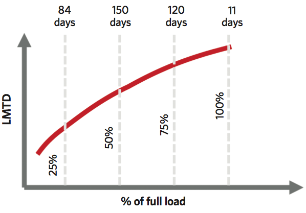
Figure 5: Relationship between required LMTD and load, together with frequency of heat demand, based on ESEER weighting factors
As seen in Figure 5, 100% load is only required (in this scenario) for approximately 11 days per year (3% of the year). So, when establishing the appropriate size of BPHE, it could be beneficial to consider making a small increase to the primary flow temperature at times of peak load, as shown in the earlier example of the determination of ΔTLM.
Example applications of BPHE
Systems employing a single BPHE between the primary system, such as a heat network, and a second system, such as a heating system in an apartment, are increasingly common. The BPHE provides a hydraulic break between the primary and secondary side, so not only can it exchange heat, but it also allows a higher-pressure primary system to deliver heat safely to a lower pressure heating system, and can potentially use different liquids on each side of the BPHE.
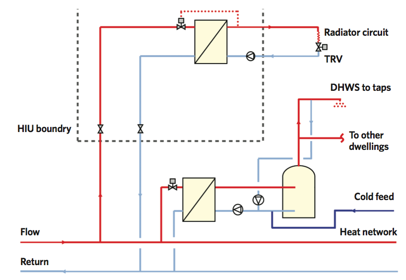
Figure 6: An example of a heating system and domestic hot water service served by two separate BPHEs selected to meet the secondary flow temperature and pressure requirements with a common primary flow (Source: COP21)
The system, as shown in Figure 6 (taken from COP 21), uses separate heat exchangers for the space heating and the domestic hot water system, with the separate BPHE designed to deliver the required approach. This same concept is employed in district heating substations, where this arrangement is categorised as a one-stage configuration. This layout is simpler than the alternative two-stage layout, which employs a pair of cascading (series-connected) BPHEs.
Large-scale BPHEs, such as that shown in Figure 7, have been developed specifically for heat networks, as well as for cooling and industrial applications that require close temperature approaches at high operating pressure. With heating capacities up to 10MW, the single high-capacity BPHE can offer an economic solution for distributed heating and cooling. As with all building services applications, this requires careful, holistic selection that should include not only an examination of the secondary load requirements, but also a careful consideration of the primary temperature profiles, to ensure delivery of energy at the lowest overall cost and environmental impact.
Figure 7: A BPHE capable of supplying 10MW heating (Source: SWEP)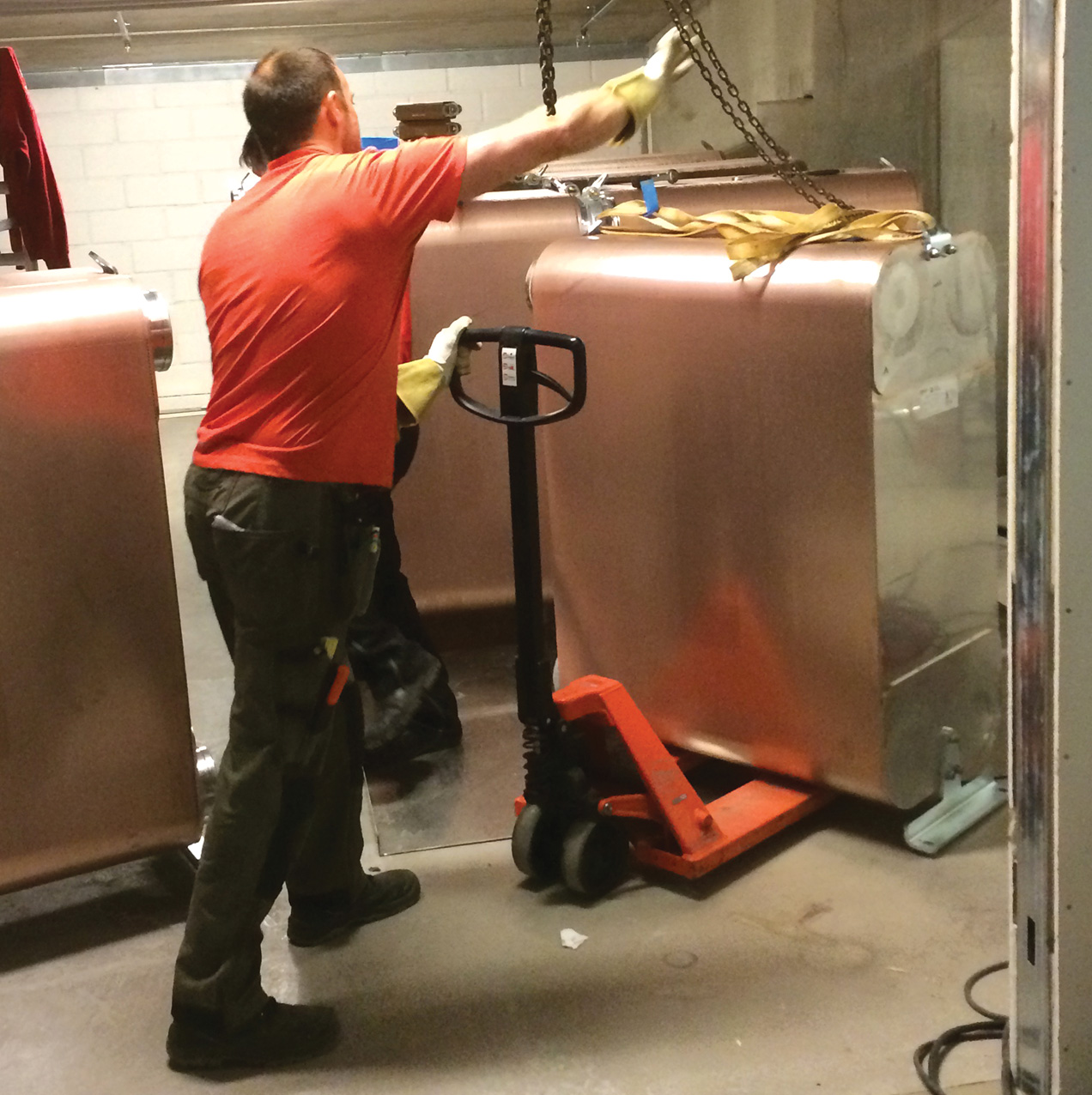
References
- COP1 Heat networks: Code of Practice for the UK, CIBSE/ADE 2015.