![]()
Thermal considerations
‘Thermal mass’ is the term typically used to indicate the ability of a building element to store heat. All materials have thermal mass. Some – such as bricks, heavyweight plaster and concrete – have higher thermal mass, while others – such as air and typical insulating materials – are lower in thermal mass.
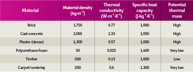
Table 1: Example thermal properties for common building materials (Source: CIBSE Guide A4)
The useful thermal mass is directly related to the value of the material’s specific heat capacity (J·kg–¹·K–¹), conductivity (W·m–¹·K–¹) and density (kg·m–³), as indicated in Table 1.
Thermal mass acts like a thermal capacitor and, just like an electrical capacitor, the thermal mass will only charge or discharge – and so alter the amount of heat stored in the mass – when there is a variation in input on either side. Practically, this means that thermal mass would not be of great help where conditions are constant on each side of the thermal mass; for an extreme example, as in a continuously operating telephone call-centre building, or data centre, located in an equatorial or polar region. And – again, just like a capacitor – the rate at which thermal mass will charge or discharge will be affected by the resistances either side of it.
High (thermal) resistance layers – such as lightweight plaster, glass fibre, mineral wool, polystyrene, polyurethane, fibreboard, cellulose, timber, floor coverings and air – will thermally isolate the thermal mass from thermal influences. So, for example, a solid terracotta floor can have its accessible thermal mass – and so its effective thermal mass – significantly diminished if there is carpet and underlay added. This will lessen the thermal ‘weight’ of the room, considering the structure as if looking from the inside. This means that the room is likely to heat up – or cool down – rather more quickly than its heavyweight equivalent.
Thermally lighter structures could be useful; for example, if the room was used infrequently, and it was beneficial to heat the room up (or cool it down) swiftly. However, this may not be so useful if the thermal mass could be beneficial for offsetting the instantaneous room heat losses or gains by acting as a thermal ‘flywheel’ – providing stability to the room temperatures. The effective thermal mass of a building structure made of several layers of material can be altered by shifting the position of the insulation relative to the layers of high thermal mass.
The thermal transmittance (U value, W·m–²·K–¹) will not be affected by the position of the insulating layers, so the steady state (and average) heat flow through the structure will be independent of the insulation position.
Not having insulating layers on the inside makes the thermal mass ‘accessible’ to the internal environment – and, potentially, to the occupants.
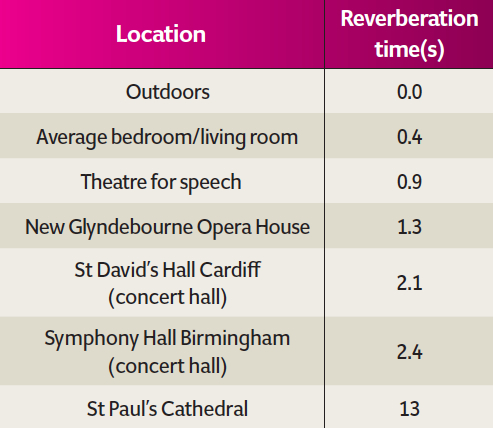
Table 2: Some typical and measured reverberation times1
Using the accessible thermal mass to store heat or ‘coolth’ – that is, by its surface temperature being respectively above or below the room temperature – will allow the surface to exchange heat with the room, and it occupants and contents, by convection and radiation. If this is synchronised properly – for example, by using cool night-time ventilation to re-cool an exposed concrete soffit that has absorbed heat during the daytime – then this exchange of heat will not only reduce the cooling (or heating) loads, but can also contribute to occupant comfort.
The influences of all the coincident internal heating and cooling loads, infiltration and movement of air, transmittance of heat through the structure and solar radiation passing through translucent surfaces – as well as the heat transfer into the thermal mass of the room – combine (alongside humidity) with the HVAC systems to produce an internal environment that determines whether occupants are thermally comfortable.
Acoustic internal environment
Room acoustics are complex, and it is likely that professional acousticians will be required to undertake a properly considered design. However, there are general principles that can help the professional lighter or building services engineer to understand the underlying issues.
As discussed more fully in the CIBSE Journal CPD article in May 2016, the actual strength of a particular sound felt by the ear is related to the sound pressure, p (Pa), that is the amplitude (magnitude) of the sound wave. For convenience, the sound magnitude is typically converted to a relative measure known as sound pressure level (dB) that relates a sound to a standardised threshold of human hearing. In an open space, the sound pressure will halve as the distance from the sound source is doubled – as the noise is spreading across an area 4π x distance;1 the reduction with distance is somewhat less in a room, because of its reflecting surfaces.
The frequency of the sound will have a significant effect on the perceived noise. Typically, human hearing is most sensitive to frequencies in the range of 3.5 to 4 kHz.2 Most sounds are made of many frequencies, but there is likely to be a dominant frequency. Low-frequency noise – such as mains electrical hum with a fundamental frequency of 50 Hz or 60 Hz, depending on global location – would need to have a sound pressure level of 40dB to be just audible, whereas a 1,000Hz sound would have to be only a few dB to be heard. The spoken word is in the range of 300Hz to 3.5kHz – consonants have most of their energy above 1kHz and are important for intelligibility. As with all real-world sounds, there are harmonics (multiples of the fundamental frequencies) included in the voice that provide a more complete sound.
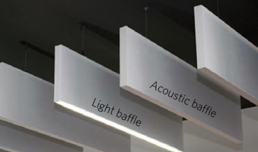
Figure 1: Simple planar baffles suspended from a soffit, arranged with adjacent ‘baffle’ LED luminaire (Source: Spectral)
The reflection of sound produces an important part of the soundscape for the listener and can enhance, or diminish, the sound clarity and their ability to hear – for example – conversation. Reflected sound accumulates to produce ‘reverberant’ sound. The early reflections – being received by the listener in less than approximately 50ms – reinforce the direct sound signal and assist in sound clarity. Then, as the time delay increases, the reflected sounds will tend to mask the original sound.
The reverberation time is used as a simple indicator of a room’s acoustic performance in relation to the reflection of sound from surfaces. As found by Wallace Clement Sabine at Harvard University at the end of the 19th century, reverberation time is proportional to room dimensions and inversely proportional to the amount of absorption present.3
Sabine empirically developed the commonly applied formula: room reverberation time (RT) in seconds for 60dB decay in sound (at 20°C) = 0.161 V/(∑Siαi), where V is the room volume (m³), Si is the area of each of the surfaces (m²), and αi is the absorption coefficient of a surface of area Si.
It calculates an estimation of the time required for the level of an impulse sound to decay by 60dB – frequency-dependent, it is a commonly used metric in the assessment of the internal acoustic environment. So, for example, a large space with tiled floors and a plastered ceiling will have a long RT, whereas a small room with a low suspended ceiling and thick piled carpet will have a much shorter RT. A reverberant room gives a higher overall sound level than a room with added sound absorption.
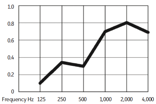
Figure 2: Sound-absorption coefficient – for example individual wire-suspended 200mm-deep baffle at 300mm centres, with 100mm clearance above baffle to soffit (Source: Spectral)
In spaces where speech is important – such as in an office or school – short reverberation times (around 0.6 to 0.8 seconds) are typical to ensure clarity and high speech intelligibility, whereas in large halls designed for music, much longer reverberation times are appropriate –or, in some cases, a matter of circumstance, as in St Paul’s Cathedral (noted in Table 2). Speech generated in a space with a reverberation time much longer than 0.8 seconds can be difficult to understand.
It is important to note that, according to BS 3882 Acoustics – Measurement of room acoustic parameters – Part 1: Performance spaces (ISO 3382-1:2009), the reverberation time of a room was once regarded as the predominant indicator of its acoustical properties but – while it is still significant – there are other types of measurements that are needed for a more complete evaluation of the acoustical quality of rooms. These other factors are beyond of the scope of this article, but they emphasise the need for the input of a professional acoustician when assessing the acoustic performance of a space.
Creating a well-lit, thermally stable and aurally comfortable room
In many commercial and institutional applications, the ceiling has historically been the principal acoustic absorber for the space. However, this can create a dilemma where the soffit is also being used for its potential thermal mass. Typically, thermally insulating materials – such as ceiling tiles – that introduce good sound-absorbing characteristics, eliminate useful access to the thermal mass offered by the soffit.
Additionally, the area of the ceiling is simply limited to the plan dimensions, so the maximum amount of absorptive material will be determined by that area. If there are other constraints – such as roof lights, sprinklers, sensors, loudspeakers and downlighters – these will reduce that available area further. To help solve this, the acoustic baffle has evolved. This is a purpose-made element that can be suspended from, or fixed to, the soffit, creating an area of selectively absorptive material – a simple suspended 200mm-deep baffle is shown in Figure 1. Manufacturers design the baffles in conjunction with laboratory tests, to establish their performance in specific mounting positions. As an example, the data in Figure 2 is for the baffle shown in the photo.
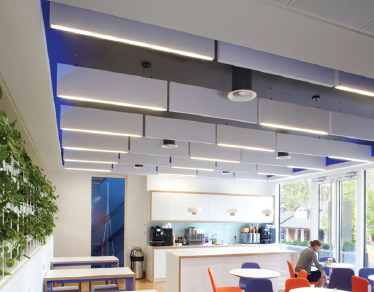
Figure 4: The baffle luminaires are mounted to match the acoustic baffles, while allowing the ventilation diffusers to pass between the ranks of baffles (Source: Spectral)
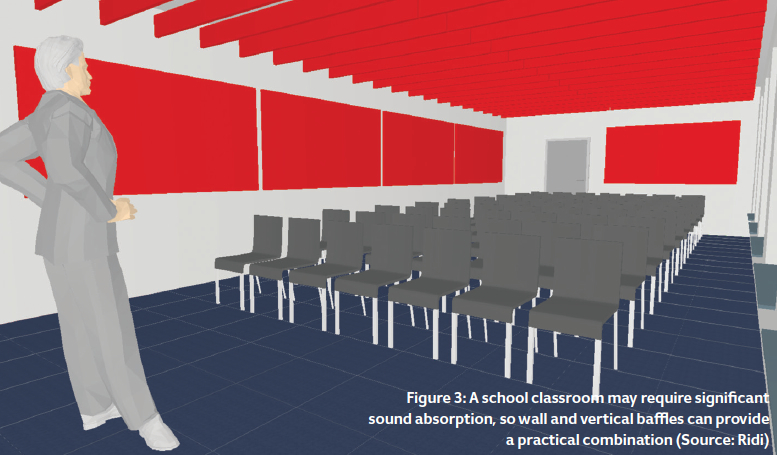
Baffles can provide a high sound-absorption coefficient, as all the surfaces will absorb sound and – when they are hung from a ceiling – sound will also reflect off the soffit onto the panel. Their orientation will alter their effect; for example, if a teacher is positioned at one end of a classroom – as in Figure 3 – baffles mounted across the space would have a greater effect than if they were mounted in line with the teacher’s line of sight.
When baffles are installed, the soffit is still partially visible to the occupants and so maintains the potential for some direct radiant heat exchange. The distance between baffles would typically be a 1:1.5 ratio, based on their depth – so a 300mm-deep baffle would be mounted at 450mm centres.
The manufacturers4 report that a vertical panel arrangement will maintain thermal exchange with a concrete soffit (by radiation and convection), with a typical reduction of 3% in cooling potential, compared with a fully exposed soffit. The baffles themselves have little thermal mass.
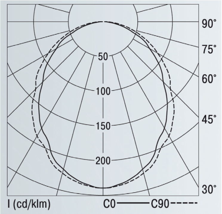
Figure 5: Example photometric polar curve for linear LED baffle luminaire (Source: Spectral)
It is possible to suspend luminaires in between the simple baffles, or to use carefully located downlighters – or daylight through rooflights – to ensure general illuminance. In some situations, this may not always yield a technically practical or aesthetically acceptable solution.
To offer an alternative (as shown in Figure 4), the general lighting can be afforded by LED luminaire systems manufactured to the same dimensions as the acoustic baffle. This can be a combined light and acoustic solution that still allows access to thermal mass.
The linear LED luminaires give an output comparable to modern fluorescent fittings, but with the attributes of LED lighting. Currently available outputs are approximately 1,600lm·m–¹ to 2,300lm·m–¹ (high efficiency to high output lamp), with an example light distribution – that will be lamp- and luminaire-dependent – as shown in Figure 5.
© Tim Dwyer, 2016.
Further reading – all available as PDF downloads:
- CIBSE Guide A1, 2016, chapter 5, provides greater detail on the application of thermal mass.
- Building Bulletin 93, 2015 – Acoustic design of schools: performance standards, 2015, published by DfE/EFA, is an excellent primer on acoustic requirements for a wide variety of spaces.
- The SLL Lighting Handbook, 2009, alongside the SLL Code for Lighting, 2012, published by SLL/CIBSE, compile comprehensive coverage of lighting design fundamentals.
References:
- Concert Hall Acoustics: Art and Science – accessed 6 November 2016.
- Hyperphysics – accessed 8 November 2016.
- Sabine, W C, Collected papers in acoustics, Harvard University Press, 1923.
- Estell, J, Designing lighting with acoustics, available from Ridi.