![]()
As with the selection of any air conditioning system, the application of a fan coil system will follow the assessment and comparison of the relative benefits of other centralised and decentralised (unitised) systems, as well as hybrid systems, natural ventilation and passive systems.
In the UK in the 1980s, FCUs found favour for air conditioning office blocks and – although originally intended for installation as free-standing, cased units – they are commonly located above suspended ceilings.1 Today, FCUs are available in many configurations2, including:
- Chassis units – normally horizontal units for mounting in a ceiling void
- Cased units – usually vertical configuration for floor mounting against a wall
- Cassettes mounted through a false ceiling
They are applied to a wide variety of building types, including a growing number of residential properties. The flexibility of locating an FCU is part of its attraction as a means of comfort conditioning a space and, as units are commercially available with up to seven air outlet spigots – for connections to flexible ductwork – several supply diffusers can serve large areas – with a uniform load profile – from one unit. There is normally a single, filtered inlet to the unit that is used both to draw in the air – often using a ceiling plenum, as in Figure 1 – and potentially to induce centrally conditioned fresh air that has been ducted towards that inlet. Manufacturers also supply additional inlet plenum arrangements, which allow the ducted inlet of air while also providing some acoustic benefit.
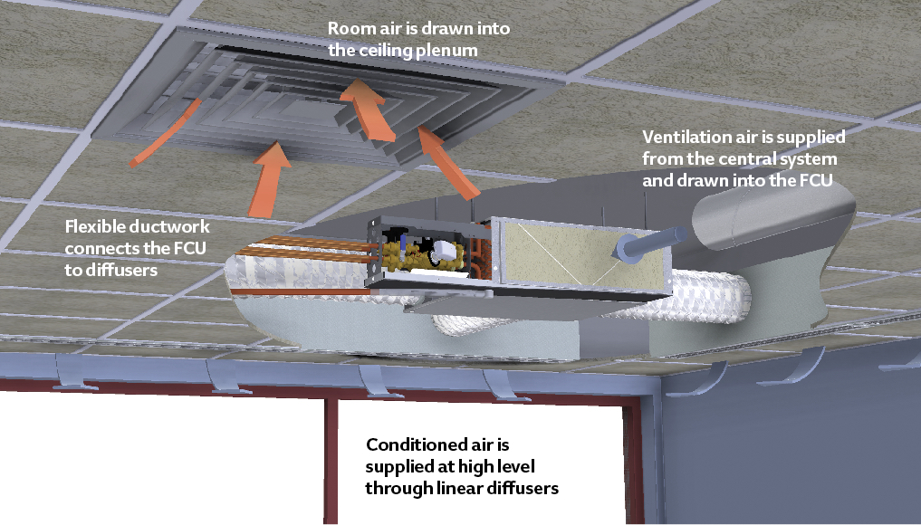
Figure 1: Example of fan coil unit installed in ceiling void, supplying linear diffusers and drawing room air through ceiling plenum, as well as ventilation air from a centrally supplied system (Source: Ruskin)
A key benefit of using a unitary-based system, such as the fan coil, is that the energy for meeting the room heating and cooling loads is transferred to the conditioned space through pipework – normally with heated or cooled water – which requires significantly less space and transport energy than would be used to convey the same amount of heating or cooling by air. Additionally, unitising the supply of heating and cooling, simplifies zoning for different occupancy and applications, local control, and subsequent reorganisation of room layouts.
The term ‘fan coil’ is applied to many configurations of appliances, but – as the name suggests – the unit will always include a fan and at least one heat-transfer coil plus some form of control) and, normally, a filter. The FCU’s function – that is, cooling or heating and possibly ventilation – will be controlled to meet the demands of the area being supplied, so that the unit can provide cooled (and potentially dehumidified) or heated air. An FCU would not normally be able to humidify air but, in other ways it is, effectively, a compact air handling unit (AHU). However, unlike most AHUs, many FCUs do not supply any outdoor air, but simply recirculate – and condition – the room air. This type of FCU is likely to be used in conjunction with a central AHU that will be used to supply the ventilation air from outdoors (often known as ‘fresh air’). The term ‘dedicated outdoor air system’ (DOAS) is increasingly used to describe the associated type of central AHU system.
The DOAS system can be sized to supply the required ventilation air for the building (for example, based on a peak design occupancy) at a vapour content – as determined by the supply air dew-point temperature – low enough to offset the indoor latent load, so controlling the indoor humidity level. Although the central system may be designed to deal with the design latent load, the FCU coil should be fitted with a properly orientated condensate tray and, where the FCU system is designed to provide dehumidification, proper condensate drainage – possibly including condensate pumps.
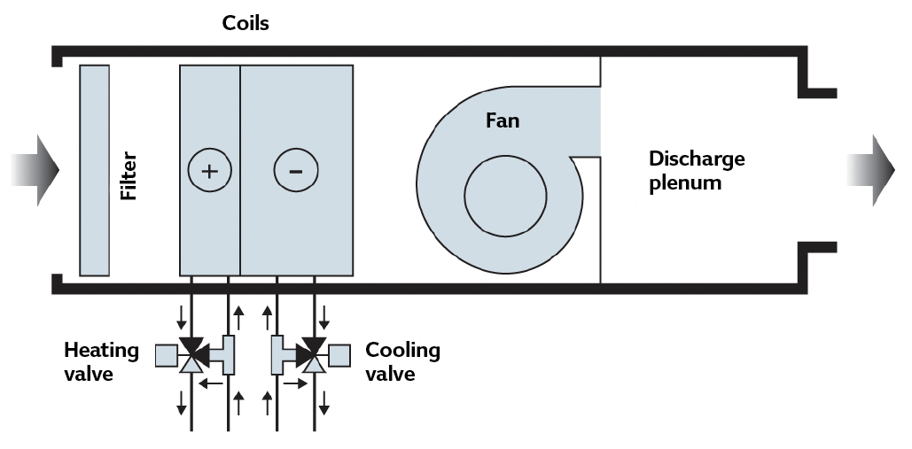
Figure 2: A generic representation of a fan coil with water-side control using four-port control valves (Source: CIBSE TM43)
The typically steel FCU enclosure will be insulated to prevent condensation on the outer surface when the unit is cooling, and heat transfer to and from the void where the FCU is mounted, as well as to reduce noise transmission from the unit. The insulation should have been selected by the manufacturer to balance the needs of good acoustic and thermal performance. Additional acoustic lining may well be added to the discharge airways to reduce noise transmission through the ductwork.
The performance of the fan/motor assembly will be a function of the fan configuration, impeller type and the motor. The fan type is typically a double inlet centrifugal (forward-curved) or tangential (cross-flow) fan with an efficiency somewhat lower than the larger, heavier, backward-curved and aerofoil-bladed fans that would commonly be used in the supply of a central AHU – forward-curved fans are better suited to low-pressure applications.3 However, unlike the central AHU fan, the pressure required from a fan in an FCU is relatively low, and the system can be designed with reasonable certainty – since the components of the whole assembly are fixed by the FCU manufacturer – who can select a fan that operates most efficiently across the FCU’s normal operational range. Modern FCU designs are optimised to reduce pressure loss, with careful design of airways, connections, filters and coil configurations.
Motors in FCUs have generally changed from being traditionally mains AC-powered to, more recently, EC (electronically commutated) DC (direct current) brushless motors. The AC to DC electronics are integrated into the motor assembly so the system is only fed by mains voltage AC power. Such motors are likely to be significantly more efficient than AC motors – by around 30% – and have a reasonably flat efficiency characteristic across the range of motor speeds. These motors are simple to speed control, so fan speed can be used creatively – in conjunction with the waterside controls – to modulate the output of the unit. A simple example, for maintaining similar air distribution patterns across the year, would be to reduce the fan speed automatically when cooling – compared with when heating – as the cooler supply air will not have the buoyancy of the heating air.
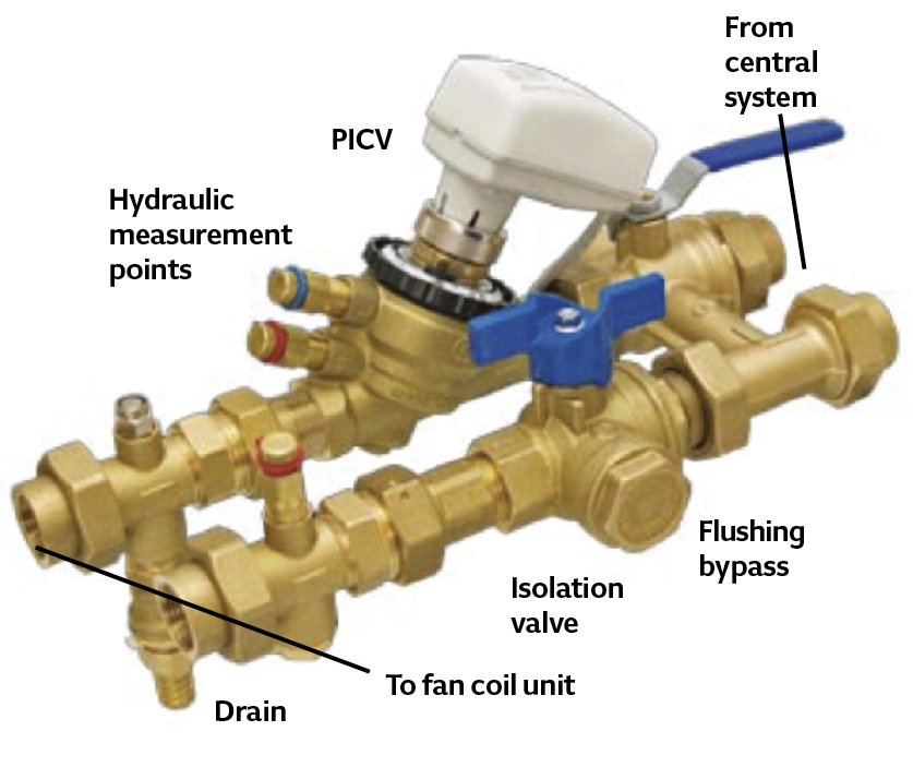
Figure 3: Example of control assembly for a fan coil unit (Source: Ruskin)
The specific fan power (SFP) – the sum of the design circuit-watts of the system fans, including losses through switchgear and controls, divided by the design air flow rate through that system – of the FCU will be influenced by both the fan and motor types, and the frictional losses from the casing, coil(s), filter, and the inlet and outlet connections. In the UK, the SFP is limited in new and replacement commercial FCU applications through the Building Regulations [Non Dom BS Compliance Guide 2013] to 0.5 W·L-1·s-1. Where there are multiple FCUs, an average SFP is determined, weighted by the electrical power consumed by each unit. This is significantly lower than the maximum SFP allowable for, say, a centralised fully ducted air conditioning system (1.6 W·L-1·s-1 for new installations). However, this value includes both supply and exhaust air. An FCU installation will also probably be installed in conjunction with a DOAS that will have a separate, additional, allowable SFP.
FCUs that can directly draw in outdoor air, as well as recirculate room air are available. This type of FCU blurs the boundaries between the comfort conditioning AHU and includes those that have traditionally been referred to as a ‘unit ventilator’. These are typically mounted on the perimeter wall to allow access to outdoor air, and have a combination of airside controls (dampers) to ensure optimum fresh air supply to a zone –for example, by making use of ‘free cooling’ – as well as managing the heating and cooling input through control of the supply to the coil. The recent edition of Faber and Kell’s seminal textbook4 notes that for units relying on direct connection through external walls for fresh air, the ‘hazards of dust and noise pollution, to say nothing of unit overload caused by wind pressure, cannot be exaggerated’.
Aside from fan-speed control, the output of the fan coil unit can be controlled by altering the supply of heated and cooled water (as in the unit in Figure 2) or, less often, through the use of dampers. This alters the air flow through separate heating and cooling coils positioned in the casing to allow different air paths.
FCUs have historically been selected primarily for their cooling potential, which has often led to heating coils that are oversized when operated at the traditional flow/return of 82°C/71°C, or even the more recently favoured 80°C/60°C. This has created opportunities5 for refurbished installations to use lower heating flow water temperatures, while still providing adequate heating output. As long as selected appropriately, new installations of FCUs can be used with wider temperature differentials, so reducing the required water volume flow (and pump power), or lower flow temperatures, to allow efficient supply from heat pump water heaters. They can also be controlled to ensure appropriate return temperatures that allow gas boilers to operate in condensing mode. These less-traditional forms of control are becoming more accessible, as FCUs are increasingly available with connections to building management systems through open protocol control networks. Cooling can also be supplied by direct refrigerant systems – often referred to as ‘DX’ (direct expansion) – and heating through electric resistance heating. This then shifts the genus of the FCU to that of the ‘split’ air conditioner, and to the family that includes variable refrigerant flow (VRF) systems.
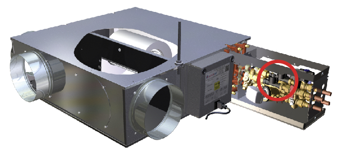
Figure 4: Fan coil unit for mounting in ceiling void showing control assembly – the sections (circled) in the assembly are piezoelectric flow measuring points (with no moving parts), for direct connection to a control system (Source: Ruskin)
The general variants of the FCU include ‘two-pipe’ or ‘four-pipe’ systems. The two-pipe FCU has one coil, so can be used for heating or cooling at any one time. If a space was to need heating or cooling consistently, then such a unit could be used as a dedicated heater or cooler. Alternatively, a ‘changeover’ system that switches the supply for the entire building or zone to heating mode or cooling mode might be used. The changeover from heating to cooling, or vice versa, is typically made manually (for example, in autumn and spring), so unusual weather patterns might make this point of changeover difficult to determine. In large systems, this can take some time, so is not an ideal solution where there is wide variance in room loads – particularly when combined with the vagaries of the UK weather.
The four-pipe system – as in the unit in Figure 2 – has two separate coils being served by heating and cooling water respectively. Practically, the copper coils of both often share the same block of aluminium fins to make the unit more compact. As the FCU is a comfort cooling device only, one of the coils would be active at any time, with a narrow ‘dead band’, where neither heating nor cooling coils are active. The coil output is normally controlled by varying the water flow rate into the coil, using an ‘equal percentage’ control valve to provide a linear relationship between heat output and valve stem position. These were traditionally two-port valves that, ideally, should have had a valve authority of 0.5, although, practically, that was difficult to achieve. In recent years, the ‘four-port valve’ had become popular – effectively, a small mixing valve in a diverting application built as a complete unit, with a bypass that connected the two tails of the coil with the flow and return from the heating or cooling water systems. This type of control maintained a good valve authority, as well as a constant flow rate in the water distribution systems. However, because of the energy benefits of variable-flow pumped water systems and the coincident development – and widespread manufacture – of two-port pressure independent control valves (PICV), these are now often used. Additionally, these are realistically able to maintain a good valve authority. They are likely to be supplied as part of the FCU package, with the appropriate design flow rates set and as part of the connection assembly, which can include such options as a flushing bypass, drain connections, and measuring stations – as shown in Figure 3 and Figure 4. The measurement points on the fan coil – potentially, pressure, flow and temperature – can readily be linked through local ‘intelligent’ controllers to the building’s management system that, in conjunction with fan speed and waterside control, can be used for energy management and comfort control.
The flexibility in positioning – as well as the potential multiplicity of the FCUs in and around the occupied space – requires a carefully considered maintenance procedure to ensure that filters, condensate drip trays and pumps, control elements and other serviceable items are properly attended. This demands proper consideration at the design, procurement and installation stages, to ensure that appropriate access can be provided with the least disruption to the building occupants. With increasing applications in residential property, there have been cases of FCUs being installed above plastered ceilings, so preventing access without destroying the finished surfaces.
The advent of this low-cost, robust technology – such as the simply controllable and efficient EC DC motor; the PICV, which provides good control as water supply pressure varies; direct links to building control systems; and optimised air paths allowing lower fan operating pressures – are all contributing to modern FCUs that are more suited to the low-energy systems needed in an increasingly wide range of applications.
© Tim Dwyer, 2016.
Further reading:
CIBSE TM43 Fan coil units offers some excellent reading on FCUs, but for explanations of more recent waterside control, see BSRIA BG 51/2014 Variable flow valve selection. CIBSE KS7 Variable flow pipework systems also provides good background on the deficiencies of older waterside control techniques.
References:
- Jones, W P, Air conditioning applications and design, 2nd Edition, Butterworth Heinemann, 1997.
- CIBSE Guide B3 Air conditioning and refrigeration, CIBSE 2016.
- CIBSE TM42 Fan application guide, CIBSE 2006.
- Oughton, D and Wilson, A, Faber and Kell’s Heating and Air Conditioning of Buildings, 11th Edition, Routledge 2015.
- CIBSE TM43 Fan coil units, CIBSE 2008.