![]()
This CPD article presents the latest efficiency improvements and some of the possible applications.
How an absorption chiller works
The principal difference between the absorption and the compression cycles is that the former is a chemical cycle and the latter mechanical.
The simplified absorption cycle is shown in Figure 1. In the absorber, the refrigerant vapour is dissolved into the liquid (the absorbent) to form a solution. The solution is composed of a salt – typically lithium bromide (LiBr), which has a great affinity with water – with water acting as the refrigerant.
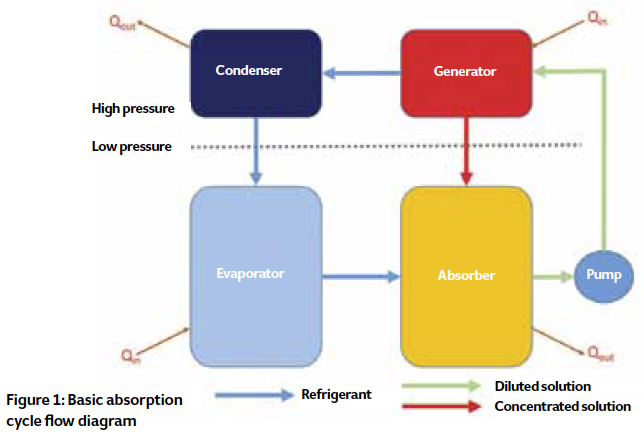
After the refrigerant vapour is absorbed in the solution, the liquid is pumped to a higher-pressure section of the chiller (the generator), where heat – typically from a waste heat source – evaporates the refrigerant (water) vapour out of the solution. This vapour enters the condenser, where cooling water – for example, from a cooling tower – condenses the water ready to pass into the low-pressure evaporator through a throttling device. The evaporator – which is of a shell-and-tube construction – operates nearly at a vacuum condition (in the shell) with a pressure of approximately 0.86 kPa.
The refrigerant (water) evaporates at low temperatures in the shell, with the heat provided from the liquid flowing in the tubes – this is a separate closed circuit that typically supplies chilled water to the building. As the refrigerant is pure water, the minimum chilled water temperature that can be achieved is 4°C, as lower temperatures could result in the refrigerant freezing. The refrigerant vapour then passes to the absorber, where the cycle recommences.
The heat balance of the flow chart shown in Figure 1 can be expressed as:
Qin + Q’in = Qout + Q’out where Qin is the cooling provided to the chilled water circuit (that is, heat is moved from the chilled water); Q’in relates to the ‘waste’ heat used to regenerate the refrigerant; Qout is the heat passed to the cooling water, so that the refrigerant vapour can condense; and Q’out is the heat removed from the exothermic reaction as the refrigerant joins with the lithium bromide.
There are two types of absorption chillers commonly available. Single-stage chillers – as discussed so far – need heat with a minimum temperature of 80°C. Double-stage absorption chillers are more efficient, but need a higher-grade heat, generally above 140°C. The sources of heat can be various; for example:
- Hot water (80-100°C)
- Superheated water (101-180°C)
- Steam (200-1,100 kPa)
- Exhaust gas or hot air (260-700°C)
- Thermal oil (110-350°C)
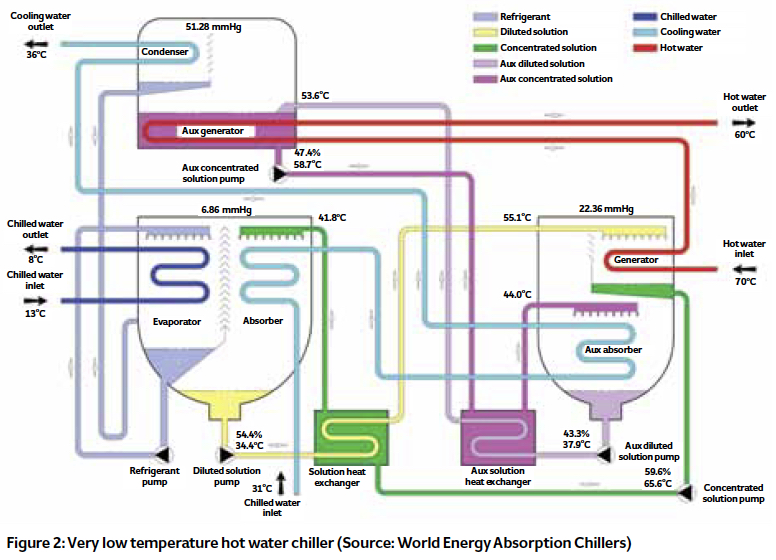
However, there are evolved absorption cooling technologies that can use low-grade heat, requiring only 70°C hot water to produce cold, as shown in the example in Figure 2.
Absorption chiller efficiency
The efficiency of absorption chillers is defined by the coefficient of performance (COP), where COP = Qc/Qh, where Qc = cooling capacity and Qh = heat input. So, for example, if a system was to use a thermal oil to transfer heat from an engine’s exhaust gas to provide the heat input for an absorption chiller delivering a flow of chilled water, the values of Qc or Qh could be evaluated from (m·Δ θ·Cp)
Where:
m = mass flow rate of chilled water or thermal oil, kg·s-1
Δ θ = temperature difference between the entering and leaving chilled water or thermal oil temperature, K
Cp = mean specific heat capacity at entering and leaving heat medium temperature, kJ·kg-1·K-1
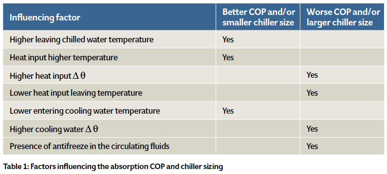
Typically, the COP for commercial absorption chillers are 0.65-0.84 (single stage) and 1.00-1.50 (double stage). The achieved COP can be affected by a number of parameters, as indicated in Table 1. The COP of absorption chillers remains practically constant down to about 50% of the design cooling load and reduces as load drops
below that.
Developments in single-stage absorption chillers to improve efficiency
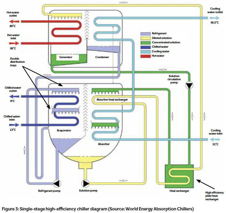
Manufacturers have been improving the efficiency of chillers – in particular, for those using low temperature heat sources such as hot water. The current highest COP for a single-stage absorption chiller is about 0.84. Incremental increases have been achieved (as shown in Figure 3) as a result of:
- Applying a plate heat exchanger in place of shell and tube, delivering a much higher heat transfer efficiency as the intermediate LiBr solution heat exchanger
- Improving the refrigerant and LiBr solution distribution inside the evaporator and the absorber, with double distribution trays
- Using shell and tube heat exchangers with higher efficiency tubes.
As well as improving efficiencies, this reduces both the required size of the unit and the quantity of LiBr solution.
Rejection of absorption chiller cycle heat
LiBr absorption chillers need cooling water to reject the cycle heat, the water being cooled with equipment such as cooling towers, dry or adiabatic coolers. Alternatively, any other available coolant process can be employed, such as sea, river, lake or underground water, or via water heat transfer to swimming pools or the ground in geothermal systems. The minimum cooling water temperature for the absorption chiller is 20°C to avoid solution crystallisation.
The heat rejected is based simply on
Qcool = Qc + Qh where Qcool = thermal power needed for the chiller’s cooling (heat rejection), Qc is the cooling load, and Qh = heat input. If the cooling water can be used for heating (for example, in swimming pools or domestic hot water pre-heating), the use of the waste heat would be maximised.
Absorption chiller applications
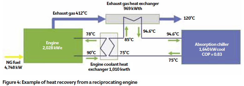
The goal of using absorption chillers is to convert as much heat as possible into cooling energy. Many waste-heat absorption chillers receive the heat from combined heat and power (CHP) plants. Most are powered by reciprocating engines and combustion turbines that convert the energy of a fossil fuel – generally, natural gas – into electricity. Being combustion machines, these reject heat that can be recovered.
Reciprocating engines have two heat outputs: high temperature (HT) from the engine exhaust gases, and low temperature (LT) from the engine and lubricating oil coolant. Normally, where CHP plants use reciprocating engines (Figure 4), the heat is recovered as hot water, and so is suitable only for single-stage absorption chillers.
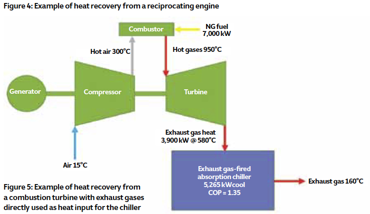
Combustion turbines have only one source of heat: high-temperature exhaust gases, as shown in Figure 5. The heat is recovered as steam, thermal oil or superheated water. Alternatively, the exhaust gases can be used directly; as it’s high-grade heat, double-stage absorption chillers can be used.
Use of chiller cooling water
In addition to the chilled water, there are applications where the chiller’s cooling water can also be used. The leaving cooling water temperature from the chiller ranges from 30°C to 40°C, and this water could be used for applications such as:
- Domestic hot water pre-heating
- Underfloor heating
- Swimming pool water heating.
For example, consider the heat rejection available, Qcool, from a high-efficiency single-stage absorption chiller with a COP of 0.83, providing 500 kW of cooling, Qc. The heat rejected, Qh = 500/0.83 = 602 kW and so
Qcool = Qc + Qh = 500 + 602 = 1,102 kW. This could be used, for example, to pre-heat water. Assuming it was used to heat water from 15°C to 33°C, 14.63 L·s-1 of water could be heated.
Absorption chillers for district heating networks
Absorption chillers can contribute to the use of the district heating resource in the warmer seasons. Instead of manufacturing large chillers for district cooling applications, discrete absorption chillers can be installed at the end user’s premises, powered by the hot water or steam coming from the district heating network.
For this purpose, high hot water Δθ absorption chillers were developed to obtain a very high difference between the entering and leaving hot water temperatures from the chiller. A high hot water Δθ helps the district heating network reduce the hot water flow rate and, consequently, the pressure drop of the network. This will reduce costs, not only because the pipes would be smaller, but also because of reduced circulation pump power consumption. Additionally, by having an outlet hot water temperature as low as 50°C the thermal distribution losses are reduced as the district heating water circulates back to the central plant.
Absorption chillers can be applied at any site that has waste heat and needs cooling. This can include:
- Small or large incineration plants – for example, hospital waste; industrial waste; municipal waste
- Biomass boilers
- Exhaust steam from steam turbines.
The resulting chilled water may be used not only in applications of air conditioning and environmental control, but also in industrial process cooling and for increasing the efficiency of combustion turbines, by cooling the turbines’ intake air to the compressor. The overall advantages of applying LiBr absorption cooling technologies include the following:
- Utilisation of otherwise wasted heat
- Natural ozone-friendly, low-cost, refrigerant (water)
- No moving parts, except for two small circulation pumps
- No vibration
- Extremely low electrical power consumption (for controls and pumps).
© Max Santini and Tim Dwyer, 2016.