
The largest growth area in the European market for active air conditioning is in variable refrigerant flow (VRF) systems, presenting an important area of application for building services professionals. This builds on previous CPD articles looking at underlying systems and technology, and considers current measures that underpin the system of energy performance labelling for space air conditioning equipment – and how that equipment is evolving, specifically to overcome areas that can potentially reduce operational effectiveness.
In Europe, over the next 10 years, growth in unit sales of VRF systems is expected to outstrip growth in other air conditioning systems.1 Coincident with this is the implementation of increasingly stringent performance requirements that allow these products to carry a CE mark and, hence, allow their use in the EU. The product labels carry the evidence of compliance with the energy performance requirements of Ecodesign directives, by incorporating the numerical indices of seasonal coefficient of performance (SCOP) and seasonal energy efficiency ratings (SEER) – terms that, in the proliferation of performance indices, may cause some uncertainty.
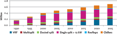
Figure 1: Estimated number of sales of air conditioning products in EU. Note that this is in terms of unit sales and not cooling capacity – further analysis is in source report1
SCOP for VRF heating performance
When considering the efficiency or effectiveness of a piece of HVAC&R equipment or system, the simple relationship of useful work done/supplied energy provides the basis of all the common measures. Coefficient of performance (COP) is typically the basis – the higher the COP the better the performance. So, considering an air to air heat pump application when heating a space:
COPH = Useful heat supplied to internal space/Power consumed by heat pump
Now, considering that the performance of any ‘heat engine’ is limited by Carnot’s theorem2 that provides a relationship for the efficiency of a ‘perfect engine’ as
TH / TH–TC
where the cold source is at TC kelvin (K) and the hot output is at TH K, to maximise the efficiency, the values of TH and TC should be as close to each other as possible. Practically, for a system running at full capacity, the effect of this will be to reduce COP by between 2% and 4% for every 1K increase in the heat output temperature (at the refrigerant condenser) or for every 1K reduction in source temperature (at the refrigerant evaporator). Therefore, for performance testing, so that systems may be compared, BS EN 145113 specifies ‘standard’ sets of design/operating temperatures that are used when manufacturers are determining the standardised COP for their heat pump device.
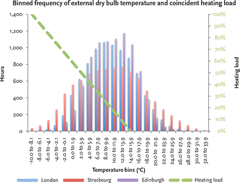
Figure 2: Example of ‘binned’ dry bulb temperatures (2K intervals) for Edinburgh, London and Strasbourg
But such COPs will not necessarily reflect the operational performance at conditions that vary from the design condition – which, of course, is most of the time. The range and frequency of outdoor temperatures can usefully be shown by employing ‘banded’ or ‘binned’ data sets. Figure 2 shows example binned outdoor dry bulb temperature data for Edinburgh, London and Strasbourg. So, for example, the 7°C bin (6.0°C to 7.9°C) occurs just under 1,000 hours a year in London and just over 700 hours in Strasbourg. As an instance of COP would only reflect a single point of operation at a particular outdoor (and indoor) temperature that would only exist for a few hours per year, the seasonal COP (SCOP) was introduced – as defined in BS EN 14825:20124 – that attempts to get closer to a measure of seasonal operation.
The SCOP effectively describes the average annual efficiency for a given heating profile. Based on a heating demand at each binned temperature, the COP is evaluated (by the manufacturer) for the heat pump operating at that condition, weighted by the number of hours in each bin, and summed to produce the SCOP. The power consumed by the heat pump includes internal parasitic loads such as controls and fans, as well as an assumed COP of 1 for any additional heat when the heat pump is unable to meet the full heating loads at lower temperatures (below the so-called ‘bivalent point’ for the heat pump).
For standardisation purposes, three European locations have been chosen to represent typical seasonal operating conditions – warmer (W), average (A) and cooler (C), relating to Athens, Strasbourg and Helsinki. The climate for Strasbourg is probably the most similar to that of the UK, although there are rather more extreme heating and cooling days in Strasbourg.
The SCOP is recorded as part of the product energy label that is a requirement under the EU Ecodesign regulations for air conditioners under 12 kW, as in Figure 3.
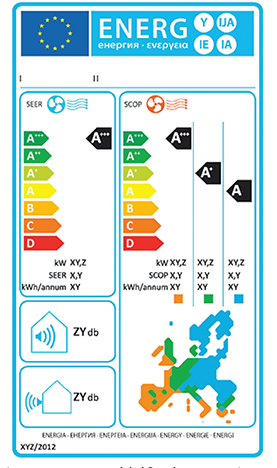
Figure 3: An EU energy label for a heat pump air conditioner under 12 kW, indicating the SCOP and SEER (as well as the cooling and heating capacity, and annual cooling and heating energy use)
SEER for VRF cooling performance
When considering the cooling performance of a heat pump, the coefficient of performance again provides the starting point, where COPC = useful cooling supplied to internal space/power consumed by heat pump. The traditionally quoted ‘full load’ COP for a system has been determined for an outdoor temperature of 35°C and indoor temperature of 27°C.
In the European regulations, the energy efficiency ratio (EER) – as defined by BS EN 14511 – is the ratio of the cooling energy delivered by the cooling system divided by the energy input to the cooling plant. This is effectively the same as the COPC. However, just as with heating, the performance of the cooling will vary throughout the operating season. Unlike heating, though, the building cooling load – and the demand on the air conditioner – will not tend to vary simply (or linearly) with changes in outdoor temperature, as it will also be affected by occupants, equipment and solar radiation.
To take account of all this, the SEER was introduced to combine the output of a pattern of cooling demands (for a typical ‘office’ building throughout the cooling season) so that different systems can be compared.
The SEER could be evaluated for a specific building/application from historical (or modelled) data of the total amount of delivered cooling energy divided by the total energy input to the cooling summed over the year. However, a standardised value is used so that it is not dependent on a specific application for the European SEER (ESEER). The climate data for Strasbourg was taken as a single reference point for the whole of Europe for the SEER, as determined from:
SEER = AxEERA + BxEERB + CxEERC + DxEERD
where for air cooled systems, such as VRF, the factors used are given in Table 1.
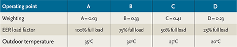
Table 1: Weightings, load factors and outdoor temperatures used in determination of SEER for VRF
This is also the SEER as referred to by the UK Building Regulations5 and simplified building energy model (SBEM)6, and is that used on the product label shown in Figure 3. It would normally be supplied by the manufacturer, together with the full load cooling capacity and power input.
Improving VRF performance
The research7 that was undertaken to underpin the Ecodesign legislation identified specific areas where the effectiveness of multi-split type systems – including VRF – was being impaired.
This is generalised in Figure 4, but it identifies two particular areas – oil recovery and compressor cycling – as contributing to reduced EER and COP at low load factors.
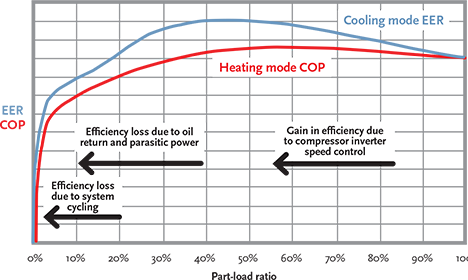
Figure 4: Figure 4: Indicative performance of a ‘base case’ VRF unit, drawn showing identifiable areas that impact on
effectiveness from data defined in Ecodesign Lot 6: Air conditioning and ventilation systems
Oil recovery – As with all vapour compression refrigeration systems, lubricating oil is carried away from the compressor with the high- pressure, high-temperature refrigerant gas. Most systems will incorporate an oil separator that minimises the amount of oil passing into the distribution system. If the oil is not reliably returned to the compressor, it can collect – particularly in the colder sections of the system – reducing the performance of evaporators, and potentially starving the compressor of lubricant.
Due to the extensive network of pipework that is associated with VRF systems, a specific (automatic) oil-retrieval mode is needed. The individual electronic expansion valves are opened and the compressor is cycled to pump the oil back around the system. This cycle will degrade the system performance, particularly when the indoor units are heating – since the recovery mode will provide a few minutes of cooling – and so should be performed as infrequently as practical. The normal method has been to run such a cycle at the some pre- determined operational interval (for example, every eight hours). However, this can lead to unnecessary operation – so needlessly degrading the overall performance – or, in extreme cases, potentially starve the compressor of required lubricant. This has been overcome by mounting a (failsafe) oil level sensor – such as the one shown in Figure 5 – within the compressor: this actuates the oil recovery cycle only when needed, so reducing the loss in system effectiveness. Depending on the temperature, the oil in the crankcase of the compressor will be combined with varying amounts of refrigerant, so it is not simply a matter of checking levels, but also – through the capacitance sensor in this example – determining the constituency of the fluid.
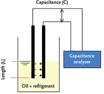
Figure 5: A sensor measures the capacitance of the refrigerant/oil mix and, with a knowledge of the temperature in the compressor crankcase, is able to optimise the oil-recovery cycle actively. [Source: LG]
Improving compressor efficiencystrong> – Previous CPD articles have spoken about the application of improved speed controllers for VRF, but there is still opportunity to improve the performance, particularly at low outdoor temperatures.
In traditional refrigeration systems, the application of a ‘booster economiser’ has been used to reduce the ‘flashing off’ of refrigerant and to enhance the amount of useful work that can be produced by the compressor. As shown in Figure 6, this effectively splits the flow of refrigerant as it leaves the condenser, and passes the smaller part through an expansion valve (reducing its temperature and pressure to an intermediate value), vaporising that part of the refrigerant and then exchanging sensible heat with the (larger flowrate, hotter) path of condensed refrigerant, so sub-cooling this main refrigerant flow before it enters the evaporator. Intermediate pressure refrigerant gas from the diverted stream enters a second stage of the compressor (or, in some traditional refrigeration systems, a separate compressor).
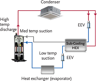
Figure 6: The application of split liquid flow and heat exchanger (economiser) with ‘two-stage’ compression provides improved performance, particularly at low outdoor temperatures (simplified diagram. [Source: LG])
Wang8 and Yonghee9 showed that the same principles could be applied usefully with the scroll compressor at the heart of the VRF system.
This has now been applied in commercially available VRF systems (referred to as ‘vapour injection’), where it can increase both the COP and EER. It is particularly beneficial at lifting the COP at low outdoor temperatures and, for one manufacturer’s range, has increased the capacity by more than a quarter, and COP by more than 10%, compared to earlier systems.
© Tim Dwyer, 2014.
Further reading
The fully explained method for determining the constituent elements of the EU Energy Label for air conditioners
More details on the determination and application of SEER is given in the Non-Domestic Building Services Compliance Guide.5
An interesting comparison of international benchmarking was undertaken by CLASP and is available at http://clasponline.org/Resources/Resources/PublicationLibrary/2012/Cooling-Benchmarking-Study This includes a detailed comparison of global SEER equivalents and the relative performance of global air conditioning unitary equipment.
References
- Ecodesign Directive – Energy-Using Product Group Analysis, Lot 6: Air conditioning and ventilation systems, Final report of Task 2, July 2012 www.ecohvac.eu
- https://www.khanacademy.org/science/physics/thermodynamics/v/carnot-efficiency-3—proving-that-it- is-the-most-efficient
- BS EN 14511:2013 Air conditioners, liquid chilling packages and heat pumps with electrically driven compressors for space heating and cooling.
- BS EN 14825:2012 Air conditioners, liquid chilling packages and heat pumps, with electrically driven compressors, for space heating and cooling. Testing and rating at part load conditions and calculation of seasonal performance.
- Non-Domestic Building Services Compliance Guide: 2013 Edition – DCLG www.planningportal.gov.uk/
- National Calculation Method for the EPBD – DCLG, www.ncm.bre.co.uk/
- Ecodesign Directive – Energy-Using Product Group Analysis Lot 6: Air conditioning and ventilation systems, Final report of Task 4, July 2012 www.ecohvac.eu
- Wang, X, et al, Two-stage heat pump system with vapor- injected scroll compressor using R410A as a refrigerant, International Journal of Refrigeration 32 (2009) 1442–1451.
- Yonghee, J, et al, Effects of Flash and Vapor Injection on the Air-to-Air Heat Pump System, International Refrigeration and Air Conditioning Conference, 2010.