The newly published Approved Document L: Conservation of fuel and power1 of the Building Regulations for England sets out requirements aimed at reducing carbon emissions by 6% for domestic buildings and 9% for non-domestic buildings (relative to Part L 2010). The challenge of delivering such savings cannot be met simply through improvements in active environmental systems. The explicit use of fabric energy efficiency targets – as added to Part L for domestic buildings – is there to ensure that the underlying permanent building components will provide a minimum level of performance, irrespective of any active systems, as well as meeting the target emissions rate that is also required under Part L.
So it is particularly appropriate that this CPD will continue the occasional series on assessing the performance of building fabric. This article will consider what determines the thermal performance of glazing, and undertake some basic window modelling, using a freely available calculation tool. This will be further expanded upon in a future CPD by comparing relative integrated performance using the free (CIBSE admittance method) PDA tool.2
The window as a thermal attenuator
The normal, primary purpose of windows is to admit daylight for practical, aesthetic and psychological reasons, while maintaining a barrier against the outdoor environment to prevent external ‘weather’ encroaching into the internal space. The thermal attributes of that barrier (the aspects that attenuate conductive and radiative heat transfer) will be part of the window’s performance criteria, alongside light transmission and noise attenuation – and all these attributes may well have consequential effects on building services. For example, the amount of useful daylight that a window will admit to a room may affect the requirement to use artificial lighting, so influencing the installed cooling load due to heat gain from the resulting luminaires and controls. Therefore, as with most architectural and building services engineering decisions, the impact of any window element must be considered holistically with the rest of the systems. This article will, however, just focus on thermal performance.
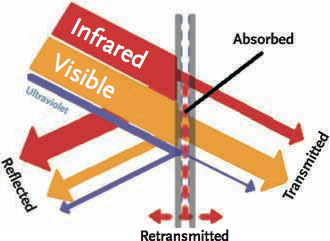
Figure 1: The simplified passage of incident solar radiation through the glazing of a window
Windows present a particular thermal challenge since, when there is a cooling load in the room (that is, the room is rising in temperature beyond the internal design temperature due to heat gains) – and while there’s a need to admit as much as possible of the visible solar energy (the higher frequency, shortwave radiation wavelengths between 380 and 700 nm) into the space (Figure 1) – it is beneficial to reduce the incoming (low frequency wavelengths between 700 nm to 1 mm) infrared radiation. Conversely, when there is a room heating load, any heat that can be provided by the sun’s infrared energy being admitted into the room might reduce the room’s heating requirements, while at the same time there may also be a need to reduce loss of (longwave infrared) radiant heat from the room to the outdoors. And at all times – subject to not causing problems of discomfort and disability glare – there is a need to promote daylight into the room. The amount of heat radiated (and absorbed) will be dependent on the emissivity of the various surfaces of glass and the surface temperatures.
Concurrent with this radiant heat conundrum there is a quandary with the conductive (and convective) heat flows through the window – both the glazing and frame. At some times of the year (typically winter), it is preferable to reduce heat flow (from room to outside), while at times of high room cooling load (and high room temperature) it may be beneficial for heat to be readily lost from the room though the window. Heat is passed from the warmed glass surfaces by radiation and conduction (being moved from the surface by convection), while some heat will be transmitted directly through the glass – as will a proportion of the visible light. The spacing between panes of glass is critical in reducing the convective forces. As the space gets wider, there is more opportunity for convective forces to move heat from one pane to another. Gases such as argon or the denser, more expensive, xenon or krypton – or even a partial vacuum – are used in place of air to reduce the convective (and conductive) heat flow between the panes. The vacuum option is particularly successful when slim retrofit windows with a small spacing between the panes are required.3
The transmitted component will depend on the optical properties of the glass, together with any reflection at surface coatings. The loss of transmitted energy will heat the glass to increase its temperature and so drive the radiant, conductive and convective heat transfers.
For older, or poor standard, installations there can be an additional significant heat loss or gain by the direct infiltration of outdoor air around the window sections.
The window U value
When a window thermal transmittance (U value) is published, it would normally be for the complete window unit, including the frame, the glazing and any glazing bars. The U value of the complete window will be dependent not only on the centre pane U value of the glazing (Ug), but also on the material used for the frame, and on the performance of the frame in thermally separating the external and internal environments. The multiple panes of glass must be thermally separated rigorously by spacers – these are typically made of low conductivity polymer or aluminium with thermal breaks. The performance of these small but essential elements can affect the thermal transmittance significantly.
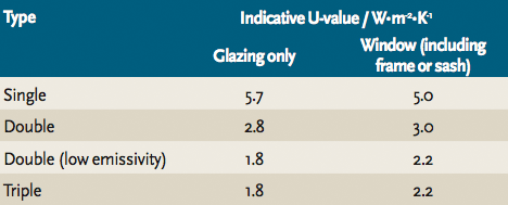
Figure 2: A sign of the advancing requirements for building performance – indicative U values for conceptual design, taken from the 2006 CIBSE Guide A
CIBSE Guide A4 tabulates some basic U values (shown in Figure 2); due to the intervening changes in required minimum U values (in the seven years since publication), only two of these would be now be appropriate for use as the minimum standard for the Building Regulations AD Part L 2013 that allows a normal maximum window U value of 2.2 W·m-2·K-1. The accelerating pace of change in the requirements for window thermal performance is illustrated by the window ‘timeline’ in Figure 3.
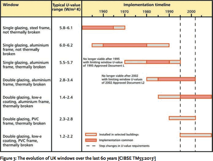
Figure 3: The evolution of UK windows over the last 60 years [CIBSE TM53:20135]
In Figure 4, the impact of the frame is shown for an extreme example where an aluminium frame with thermal breaks (with a frame U value of 3.4 W·m-2·K-1) influences the overall U value of a window. The figure illustrates the use of different glass combinations (and their respective values of Ug) with variations in percentage of the window area occupied by the frame, indicating that – even with relatively high performing glazing – an increasing proportion of high thermal transmittance frame can produce unacceptably high U values. Frames are available with far lower U values than this simple aluminium example, including those made of timber and glass fibre.
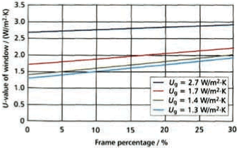
Figure 4: Framing percentage effects on window U values [CIBSE TM35 20046]
U values for windows well below the UK’s Part L requirements are readily achievable. A notable example was the recent work on the Empire State building in New York, where refurbished windows contributed about an eighth of the predicted 38% saving in the refurbished building’s energy use.7 All 6,514 of the double glazed windows were upgraded. The north-facing windows were refurbished using low emissivity film suspended between the two panes of double-glazed windows (using the original frames) to provide a U value of below 0.8 W·m-2·K-1 (using 90% krypton gas to fill the cavity), as shown in Figure 5.
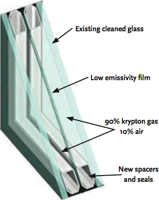
Figure 5: The Empire State Building’s existing windows were removed, cleaned and retrofitted with an intermediate low-e film – the refurbished windows were kilned to shrink the film to provide a taut finish
Glass solar heat gain coefficient
Glass is naturally relatively opaque to infrared (the heat), so the first pane will absorb radiated heat and potentially re-radiate that heat from its other surface, depending on the emissivity of that surface. ‘Low-e’ glass is commonly employed to reduce the emission – where one surface of the glass (often the surface facing the cavity) has been treated during manufacture with a specific coating. The emissivity of plain glass is about 0.84; depending on the coating, this could be cut down to 0.02 – so reducing the radiant heat transfer to just a few per cent of that of plain glass. Broadly, where there is a need to reduce solar gain, the coating would be on the inner surface of the outermost pane, and where heating is the key requirement, the inside pane would incorporate a low-e surface. Traditionally, the coatings that were used were ‘hard’ pyrolytic (added while the glass was soft) and ‘soft’ sputtered (metal deposited on glass sheets). The soft coatings could produce the most effective low emissivity surfaces but were less durable. However, the durability of some ‘sputtered’ coatings is now such that they may be used on the exposed – typically indoor – surfaces and can contribute to a very low Ug value for the glazing.
The total solar heat gain coefficient, g, (or SHGC), is the proportion of heat from incident solar irradiation that enters the room. Where windows are predominantly used for passive solar heating, a high SHGC could be appropriate; conversely, windows designed primarily for situations where cooling prevails must have a low SHGC, to exclude significant amounts of the solar radiation. There is normally some trade off, as the visible transmittance (VT) – the fraction of the visible spectrum of sunlight that passes through the window – will drop as the SHGC reduces.
The characteristics of glass may be dynamically altered with the advent of mass produced photochromic glazing systems. These are being evaluated in many parts of the world.
Historically, the shading coefficient (SC) was used to define the glass performance (relative to the solar thermal performance of simple 3 mm glass). This term it is practically redundant, but if needed for approximate purposes, SC = g/0.86.
Computer modelling to compare potential window performance
It is possible to use tabular data and look up tables to determine the values required to model the performance of windows in a building. CIBSE Guide A includes such a method for the calculation of window U values (as illustrated in the CIBSE Journal CPD article in June 2011) that accounts for both the frame and glazing. However, in practice the values would be provided by the glazing system manufacturer or, if more concept detail needs to be investigated, by undertaking a calculation in accordance to the BS ISO 10077.8
However, the profiles of the materials that make up the frame, the interaction between each layer of glazing and the other parts of the window, together with the complex path for radiant heat transmission through glass and solar control surfaces, means that the task is most appropriately undertaken by computer-based tools. There are some excellent (and free) pieces of software that can be used to explore and compare the potential performance of windows, such as the freely available LBL WINDOW9 package to determine the thermal properties of the glazing unit. (This would probably be used in conjunction with a tool such as THERM that is used to establish the frame thermal performance – again, see CIBSE Journal CPD, June 2011.)
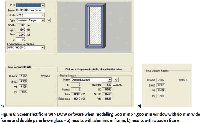
Figure 6: Screenshot from WINDOW software when modelling 600 mm x 1,500 mm window with 80 mm wide frame and double pane low-e glass – a) results with aluminium frame; b) results with wooden frame
Such a tool is useful to evaluate, simply and quickly, different glass, solar film and glass coatings that can then be applied with a variety of frame solutions. The data can then be used as an input to a building thermal model. As an example, using WINDOW software as shown in Figure 6, the impact of changing the frame from aluminium to wood may be examined.
The CIBSE admittance method applies solar factors that fit in with its 24-hour cyclic modelling technique, known as the mean, and the alternating solar gain factors that have been further developed to consider the proportion of radiant and convective heat flows. Practically, these may only be established with software that is normally embedded into admittance method tools.
© Tim Dwyer, 2014.
References
- Approved Document L – Conservation of fuel and power, DCLG, 2013, www.planningportal.gov.uk/buildingregulations/approveddocuments/partl/
- Passive Design Assistant, PDA – freely downloadable, www.arup.com/Publications/Passive_Design_Assistant.aspx, accessed 30 November 2013.
- Heath, N. and Baker, P., Slim-profile double-glazing in listed buildings – Re-measuring the thermal performance, Historic Scotland Technical Paper 20, 2013.
- CIBSE Guide A Environmental Design, CIBSE 2006, Chapter 3.
- CIBSE TM53 Refurbishment of non-domestic buildings, CIBSE 2013.
- CIBSE TM35 Environmental performance toolkit for glazed facades, CIBSE 2004.
- www.nrdc.org/greenbusiness/empire-state-building-windows.asp, accessed 30 November 2013.
- BS EN ISO 10077, Thermal performance of windows, doors and shutters. Calculation of thermal transmittance. Numerical method for frames, BSI 2012.
- LBL WINDOW software, http://windows.lbl.gov/software/window, accessed 30 November 2013.