
There is a clear imperative from the UK government1 for low carbon biomass heat, and with support under the Renewable Heat Incentive (RHI), biomass boilers have the potential to provide a reduction in carbon dioxide (CO2) emissions as well as offering a financial benefit. As with all engineering design, and particularly low carbon or ‘renewable’ technologies, proper consideration is essential to ensure a beneficial – and socially acceptable – solution.
The UK has a binding target under the EU Renewable Energy Directive 2009 to source 15% of its overall energy from renewable sources by 2020. However, it is currently struggling to meet that obligation.2 The UK bioenergy strategy3 suggests that bioenergy has the potential to provide approximately 30% of the 2020 target through biofuels, biorefineries and the recovery of energy from the biomass portion of waste (including anaerobic digestion), so as a way of driving the development of appropriate systems to meet the directive, there is strong support for deployment of biomass heat – primarily driven by the RHI.
Not only is there wide variation in biomass boiler design, but there are also ranges of different biomass fuel types. The vast majority of installations in the UK are ‘woody’ or ‘solid biomass’ – typically wood pellet or wood chipfed units. This CPD module deals exclusively with ‘mid-size’ automatically fed chip and pellet systems for commercial applications.
Equally suited to new build and retrofit schemes, with correct hydraulic design, commercial biomass boilers can be integrated into existing systems, and are best employed as part of a bivalent system (sharing the maximum load with a gas or oil boiler). In comparison to a fossil-fuelled boiler there are, however, significant technical differences in design, operation and maintenance that must be understood and accommodated in order to achieve a successful outcome.
Fuel quality and storage
Perhaps the most important factor to consider when appraising a potential biomass installation is sourcing a fuel supply of an appropriately high standard, and provision for its storage on site. Pellet/chip size, moisture content, calorific value and fuel constituents all have a major bearing on boiler operation.
The sustainability of fuel supply is central to the concept of wide scale deployment of biomass heating. The main source of biomass in the UK is timber from forestry, which falls under the remit of the Forestry Act (1967). The Central Point of Expertise on Timber Procurement (www.cpet.org.uk) gives advice on how public sector buyers and their suppliers can meet the UK government’s timber procurement policy requirements and demonstrate that timber supplied is legal and sustainable.
The standards governing the quality of fuel available for wood pellets and wood chips are, respectively, BS EN 14961-2:2011 Solid biofuels. Fuel specifications and classes. Wood pellets for non-industrial use and BS EN 14961-4:2011 Solid biofuels. Fuel specifications and classes. Wood chips for non-industrial use, specifying limits on size, chemical and physical properties. Ensuring the supplied fuel is in accordance with relevant quality standards is essential in ensuring effective boiler operation.
Low moisture content is key to effective combustion. Pellet fuel produced in accordance with quality standards typically has lower than 10% moisture content and, depending on the source and type, wood chip may be closer to 30% (when harvested, timber will have a moisture content typically around 50%, and above 55% moisture content, the fuel is unlikely to burn). Typical calorific values are given in Figure 1. Boiler manufacturers will specify a moisture tolerance range. Excessively high moisture content can lead to incomplete combustion, releasing black smoke and tars that can coat internal heat exchanger surfaces and cause damage to fuel delivery systems.

Figure 1: Typical calorific values of ‘woody’ biomass fuels
A wide variety of fuel storage options are available, from purpose built rooms to prefabricated silos and containerised stores, with automated feed systems typically comprising a mechanical auger or pneumatic arrangement. Physical size, maintenance requirements and access for fuel delivery trucks all require consideration. For these reasons, the installation of biomass plant in dense urban environments can pose logistical challenges.
Handling and storage of fuel can also present safety issues. For example, wood chips with high moisture content may degrade and decompose in storage, losing calorific value. In certain conditions, there can be mould growth that – in common with wood dust – if inhaled can cause respiratory problems. When wood pellets are blown into a store upon delivery, a proportion of ‘break up’ can happen, leading to a suspension of dust in the air that can pose an explosion risk. Furthermore, in the case of pellets, it has recently been reported that stored fuel can release carbon monoxide (CO), making a robust safety procedure essential when working on or inspecting enclosed fuel storage areas – including provision for ventilation and supervision. Established guidance is provided by the UK Health and Safety Executive (HSE) (www.hse.gov.uk/confinedspace/), while the Dangerous Substances and Explosive Atmospheres Regulations 20025 (DSEAR) provides further information on control of such risks. (Also, see Further reading section below.)
Combustion process
Figure 2 shows a diagrammatic arrangement of the combustion process of an example midscale biomass boiler, incorporating a moving grate fuel bed and cyclone flue-cleaning device.
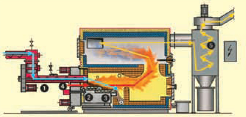
Figure 2: Typical biomass boiler combustion process (Source: Potterton Commercial BBS)
- Fuel is automatically fed into the combustion chamber of the boiler. The fuel is ignited by a blown hot air ignition system.
- The automated grate movement evenly spreads the fuel at the point of combustion for optimum burning efficiency.
- Relatively small amounts of ash residue (from 0.5% to 2% dry fuel weight) will remain when the fuel has been fully burnt. The grate movement propels ash to a mechanical screw that removes the ash into the ash box.
- When the unit is first ‘fired’, hot air is blown in at the fuel entry point. The hot air ignition system turns off when the flame is established.
- The hot gases and particulates are drawn through the boiler through a multi-cyclone collector to remove the majority of the particulates (roughly 2% of the total ash will be carried along with the combustion gases6), which are collected in the ash box at the base of the collector. The remaining flue gases are discharged to the atmosphere.
The fuel feed rate will modulate according to the heating system demand. Typically controlled by a ‘lambda sensor’, the rate of excess air supplied into the combustion process is critical to derive the highest efficiency, together with minimising the production of CO, NOx and soot.
The combustion of biomass fuel typically generates a higher level of polluting emissions than that of a gas fired boiler – although not as high as other solid fuels – so compliance with local requirements on clean air and particulate emissions is critical.
The Clean Air Act (1993) regulates particulate emissions from residential and industrial combustion sources, and allows areas to be designated as smoke control areas (SCAs). Under the Environment Act 2005, local authorities throughout the UK have a statutory duty to review and assess air quality in their area against the objectives set for nitrogen dioxide (NO2), particles measuring 10μm or less (PM10), sulphur dioxide (SO2) and other gases.
To enable the wider adoption of biomass heat, boilers can be approved for operation in designated SCA and, subject to the maximum concentrations of particulate matters and NO2 not being exceeded in a given area, approval for a biomass installation should be possible.
System hydraulics and buffering
Biomass boilers are typically less responsive than modern condensing boilers, with less effective modulation and lower turn-down ratios. For this reason, it is recommended that the biomass boiler is sized to cover the base heat load of the building, with condensing gas boilers meeting peak load requirements. This enables the biomass boiler to run for longer periods without load cycling; this is important, as multiple boiler starts over a short time period can result in incomplete combustion and a rise in pollutant emissions.
A buffer vessel is essential in most installations – firstly, to allow longer run periods and smooth out peaks in system demand, and secondly, because when the boiler stops firing there can be a great deal of residual heat in the fuel bed and refractory lining that must be dissipated, which is typically undertaken by employing a pump overrun control.
Sizing of the buffer store will vary by boiler design, fuel type and the system it is serving – manufacturers’ advice will be required. Boilers with a lower water content and good modulation may only need 10 litres per kW output, whereas larger chip-fed appliances may require upwards of 50 litres per kW.
Figure 3 shows a typical bivalent system layout with a buffer vessel, peak load boilers and a low-loss header.
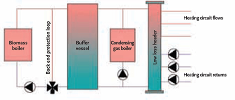
Figure 3: Simplified schematic of a typical bivalent biomass system
With this arrangement, it is typical for the condensing boilers to operate with a return temperature of around 50°C to ensure optimum efficiency. Many biomass boilers will require a return temperature of between 60 and 65°C, dependent upon fuel moisture content, to prevent corrosion of the heat exchange surfaces.
Therefore, a back end protection loop – comprising a three-port control valve and shunt pump circuit – is a common arrangement, thereby bypassing the buffer vessel until the boiler loop is up to an acceptable temperature.
Renewable Heat Incentive for biomass
Payments are based on kilowatt hours (kWh) of metered generation for heat produced by the biomass plant that is used for an eligible purpose (space heating, hot water production and some processes). Tariff levels are split by the installed thermal output (kWth) of the biomass plant, as detailed in Figure 4.
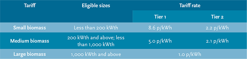
Figure 4: RHI tariff levels for biomass installations (July 2013)
Affected installations covered by these tariffs will receive, each year, a higher Tier 1 tariff for the initial proportion of heat (an energy equivalent of the total installed load output for 1,314 hours per year) and lower Tier 2 payments for the remainder. (So, under current RHI arrangements, there is the potential for unscrupulous or poor design producing oversized installations that would benefit from a larger proportion of Tier 1 payments.)
Heat meters, compliant with ‘class 2’ requirements of the Metering Instruments Directive (MID Annex MI-004), must be employed to provide heat delivery data for claims. Ofgem publishes guidance on the requirements for the number and placement of such meters, which depends on the number of heat sources and complexity of the system. In the case of system designs including a back end protection loop, it is essential that this is excluded from any metering, as the heat is not deemed ‘useful’; typically, a meter at the inlet of the buffer vessel will suffice.
From the date of a successful application, the tariff is claimable for a period of 20 years for biomass installations – providing the plant remains in operation – with annual adjustments of tariff levels in line with the Retail Price Index (RPI)
Built into the RHI scheme is a ‘degression mechanism’ that will instigate a reduction of the tariff level in the event of a particular technology reaching 150% of the Department of Energy and Climate Change (DECC) predicted expenditure in a budget year. During May 2013, the ‘medium biomass’ category reached its degression trigger point, meaning that new applicants for the scheme since July 2013 face tariff rates 5% lower than those offered on earlier installations.
Maintenance
For the operational phase of a project, it is essential to define a robust maintenance regime for biomass boilers. In general terms, to ensure efficient operation, maintain clean flue gas emissions and prevent damage to internal components, the biomass plant will have greater maintenance requirements than a gas boiler. Dependent on the design of the boiler and any ‘self clean’ functionality, it may be necessary to complete weekly tasks such as emptying ash bins or brushing flue ways. Self-cleaning units can reduce this interval and provide a degree of automation to the maintenance regime.
Packaged plant rooms
A complete biomass solution includes fuel storage, fuel delivery system, buffer vessel, backup boilers, hydraulic integration and controls, together with requirements for maintenance access and fuel delivery. Incorporating all of this into an internal plant room can prove challenging in terms of space availability, especially in the case of refurbishment schemes.
To this end, containerised plant rooms (as shown in Figure 5) – including all required system components, flues and external connection points – are becoming available. This approach offers significant benefit in terms of site assembly time and ensures a consistently high quality design and fabrication. Following recommendations in the Egan Report, it is anticipated that offsite prefabrication has the potential to decrease costs by as much as 30%.
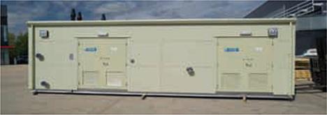
Figure 5: Example of a prefabricated, packaged plant room
The application of biomass technology for providing heating for buildings is, of course, not new. However, new systems that include benefits such as more reliable automatic fuel feeds, and improved burner and emission controls, together with a maturing fuel supply market, greater government assistance and increased market competition, are opening up the potential application of biomass boilers.
© Jeff House and Tim Dwyer, 2013.
Further reading:
CIBSE Knowledge Series 10 : Biomass Heating is a good introductory text, and the freely downloadable Biomass heating: a guide to medium scale wood chip and wood pellet system from the Biomass Energy Centre provides an excellent reference. For practical health and safety provisions, there is an excellent free guide Health and safety in biomass systems: Design and operation guide, published by the Combustion Engineering Association.
References
- The Future of Heating: A strategic framework for low carbon
heat in the UK, DECC, 2012. - Renewable energy progress and biofuels sustainability,
(ENER/C1/463-2011-Lot2) EC, 2012. - UK Bioenergy Strategy, DECC, 2012.
- Typical calorific values of fuels,www.biomassenergycentre.
org.uk/portal/page?_pageid=75,20041&_dad=portal
&_schema=PORTAL accessed 28 June 2013. - The Dangerous Substances and Explosive Atmospheres
Regulations, HSE 2002,
www.hse.gov.uk/fireandexplosion/dsear.htm - Palmer, D. et al. Biomass heating: a guide to medium scale
wood chip and wood pellet systems, Biomass Energy Centre
(www.biomassenergycentre.org.uk), 2011. - Palmer, D. et al. Biomass heating: a guide to feasibility
studies, Biomass Energy Centre
(www.biomassenergycentre.org.uk), 2011.