
Combined heat and power (CHP) can provide an efficient system by making both generated electricity and recovered engine heat for immediate local use. Through generating, and effectively consuming, heat and power simultaneously, CHP can reduce primary energy use by up to 30% compared to the more conventional methods, such as condensing gas boilers and grid supplied electricity.
This CPD will concentrate on aspects of small-scale CHP, commonly referred to as ‘packaged CHP’, as the units are typically delivered to site as a complete item, ready for installation. CHP systems are commonly classified based on electrical output (kWe), as shown in Table 1.
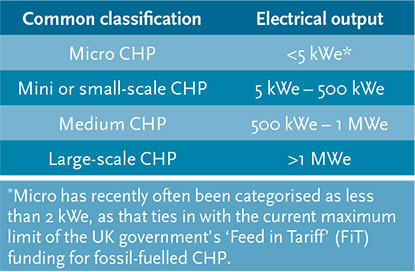
Table 1: Typical classification of CHP systems
As shown in the example mini-CHP in Figure 1, the engine known as the ‘prime mover’ drives a generator to produce electricity and recovers heat from the engine coolant, exhaust gas or – in the case of a larger steam turbine system – through spent steam.
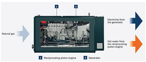
Figure 1: Packaged small-scale CHP (Source: Bosch)
CHP effectively works as a localised power station close to the point of electricity and heat demands, avoiding transmission and distribution losses and utilising the waste heat locally, leading to higher fuel efficiency and potentially lower carbon emissions. Most ‘small scale’ CHP installations in buildings are packaged units, based on natural gas-fuelled reciprocating engines, with an electrical output normally less than 500 kWe. Small-scale gas turbines are also available that have lower maintenance requirements, but also lower electrical efficiencies.
The primary energy saving for CHP may be compared1 to traditional systems by considering the typical output from a CHP that is consuming 100 units of natural gas. This will generate 35 units of electricity and 45 units of useful heat.
Conventional grid-based electrical generation at 40% efficiency to produce 35 units electricity (40% = energy used at end user/energy consumed at power station)
= 35/0.4 units of fuel = 88 units
Conventional heating to produce 45 units of heat at 80% efficiency
(80% total fuel efficiency of commercial heating system)
= 45/0.80 units of fuel = 56 units
The total fuel required, using a conventional supply to match the CHP output
= 88 + 56 = 144 units
So the potential saving in primary energy is about 30%.
CHP can use many forms of fuel such as oil, biomass, bio liquid and bio methane, but the most frequently used fuel is natural gas.
The generator and electrical power production
Asynchronous or synchronous generators are typically used to produce three-phase electricity at 50 Hz 400 V for connection into the low voltage site distribution system. The generated power would normally be used locally. It is possible to export power into the grid with agreement from the local district network operator (DNO), but for natural gas fuelled mini-CHP module, this is generally uneconomical – particularly as the price paid by the networks could be just half of that paid for buying in electricity. When establishing the potential benefits of applying CHP, the effect on the mains electrical supplier must be considered, as both peak electrical demand and overall site consumption will reduce, affecting the negotiated tariff costs.
The potential for CHP
At the end of 2010, there were just under 1,200 non-industrial CHP installations in the UK2, and the introduction of UK government’s ‘Feed in Tariff’ (FiT) payments (guarantees to pay a fixed tariff for each kWh of electricity generated, and an additional payment for each kWh of electricity exported to the grid) has accelerated the adoption of micro-CHP systems, with more than 4003 having been installed since 2010. The trial undertaken by the Carbon Trust (reported in 20114) of 87 micro-CHP installations in typical UK households and small commercial applications, found that the larger domestic systems – using more than 15 MWhth heating per year – and small commercial premises were most likely to benefit from savings in carbon, with average CO2 savings of up to 16%. On average, small domestic installations benefit (in carbon terms) by a few per cent compared to using a condensing boiler and grid electricity. The first three years of the UK government’s FiT has provided an incentive for micro-CHP (<=2 kWe), helping to boost the adoption – and expertise in installation – of small gas-fuelled units. This is likely to improve the performance of future installations.
Using factory produced small-scale CHP schemes may potentially achieve peak operating efficiencies of up to 90%. The seasonal efficiencies will be dependent on the matching of the year-round local thermal load to the heat produced by the CHP. Applications that are particularly suitable are those with consistent heating and/or hot water loads alongside electrical demand, such as hospitals, leisure centres with swimming pools, and factories with processing requiring heat/hot water/low pressure steam or district heating systems.
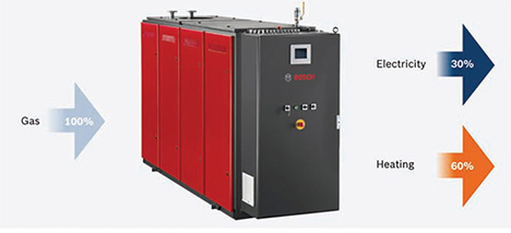
Figure 2: Potential peak operating efficiencies for mini-CHP (Source: Bosch)
Economic and environmental considerations
The CHP is powered using a lower cost fuel, such as natural gas, to produce energy with a higher value in the form of electricity. The difference between the cost of these two fuels (known as the ‘spark-gap’) has a most significant effect on the economic viability of a project. As the spark-gap increases, the payback period for the capital (and operational) investment will reduce. Manufacturers quote a product life of around 10-15 years of operation (with appropriate maintenance), and although fuel prices will change over that period, the separate fuel prices typically increase together to maintain a practical spark-gap.
To provide increased benefit, a CHP scheme should operate as many hours per year as possible. As a general ‘rule of thumb’, the recommended minimum running hours for financial success is an equivalent of 12 hours per day, with well-selected, designed and operated systems potentially providing payback within five years. In the UK, the heat demand is inevitably seasonal. However, by using heat-driven absorption chillers, there
are opportunities to extend the season so that heating base load is increased during the summer months, enabling a more effective use of the CHP plant. Symbiotic energy-linking with nearby users that have complementary heat/power profiles can provide highly effective solutions – for example, a tomato farm and supermarket, or a university administration block and student residences.
Apart from a potential reduction in carbon emissions, there are a number of financial incentives in the UK to encourage the application of CHP systems.
Natural gas-fuelled systems with an electrical output no greater than 2 kWe are currently eligible for funding under the FiT scheme.5 Systems (up to 5 MWe) fuelled with biogas from anaerobic digesters are also eligible for FITs, as well as the Renewable Heat Incentive (RHI) for up to 200 kWth.6
The Enhanced Capital Allowance (ECA) scheme allows businesses to claim 100% first year capital allowances on investments in qualifying energy saving technologies and products that can include CHP.
The Quality Assurance for Combined Heat and Power (CHPQA7) provides a standardised method to compare the effectiveness of CHP systems, through a quality index (QI) and power efficiency. This provides the principal evidence required for determining eligibility of CHP schemes for ECAs – see CHPQA document Guidance Note 42 – and Climate Change Levy (CCL) exemption.
Qualifying CHP projects can be exempt from paying CCL on the gas used to fuel the scheme, while also benefiting from not having to pay CCL on the electricity generated. For larger consumers (with total electricity consumption under 6,000 MWh per year), CHP can reduce the liabilities under the Carbon Reduction Commitment (CRC).8
‘Good quality CHP’ can also attract business rates exceptions.9
Additionally, the CHP can enhance the environmental rating of a building. For example, a properly installed, commissioned and monitored system can attract BREEAM credits for areas including emissions, energy monitoring, low and zero carbon (LZC) technologies and innovation.
Sizing CHP schemes
This requires historical or projected data about heat and electricity use. From this data, an annual profile may be established for heat usage and concurrent power demand that will assist in determining the base load for the building. As indicated in Figure 3, the profiles of heat load will be highly dependent on the building type, and this will strongly influence the installed capacity of CHP (keeping in mind the ‘rule of thumb’ average 12 hours-a-day, 4,500 hours-per- annum breakpoint for economic viability).
However, proper consideration requires half-hourly or hourly data of concurrent heat and power usage, as using time frequency data (see Figure 3) may conceal periods of mismatch between the power and heat loads. Similarly, temporal data will enable spreadsheet models to be created that can include the vagaries of fuel tariffs. A suitably sized CHP can then be matched to the profile, which typically may be under 20% of the peak heat load.
It is possible to have electrically-led operation, where the CHP is operated to primarily meet an electric load, but this will inevitably lead to the wasteful rejection of heat. Although there could be occasions where this might be economical (for example, in off-grid locations), the total
efficiency of the scheme will drop dramatically.
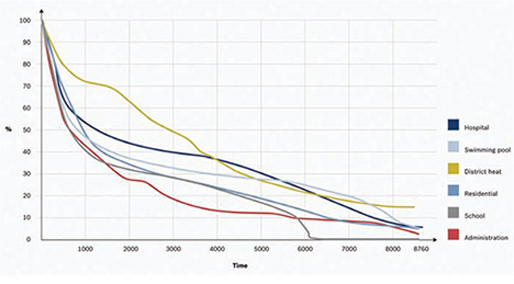
Figure 3: Typical heat load profile examples for different building types (Source: Bosch)
Hydraulic integration
Figure 4 shows the typical water circulation around a CHP unit. A pump circulates return water first through the oil cooler, followed by the engine block and on to the heat exchanger around the exhaust system, before finally transferring the collected heat via a plate heat exchanger to the heating circuit. With this configuration, the return temperature to the CHP must not fall below 70°C, as this can damage the engine. Some CHP units have an internal ‘back end protection’ system fitted to maintain the return temperature or, if it is not incorporated, an external (but closely coupled) back end protection system is used.
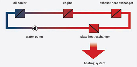
Figure 4: Simplified CHP hydraulic loop (Source: Bosch)
The CHP units will operate in conjunction with other heat sources, such as condensing boilers. To help meet peaks in demand, a thermal store is often incorporated into the system and, for mini-CHP, this is typically sized10 to store the heat from one hour run time of the CHP. The thermal store and CHP should be connected into the system so that the heat from the CHP is used in preference to any other non-renewable heat source, acting as the ‘lead boiler’. This will extend the period during which the CHP may generate electricity, as well as reducing the call on the more carbon-intensive heat sources, even at times when the load is below the point where the CHP plant can operate effectively. This adds further complexity to the economic modelling of the CHP system, as it allows heat to be supplied from that generated by the CHP even at times, such as
at night, when the electrical tariff would make it uneconomic to operate the engine. Using a predictive control strategy, the charging of the thermal store can be optimised to maximise the operational hours of the CHP.
A CHP installation can offer a sound financial investment, but this is dependent on a rigorous site evaluation and pre-selection, appropriate sizing, holistic design, installation, and a fully monitored and maintained operation.
© Tim Dwyer, 2013.