The challenges of establishing demand controlled mechanical ventilation (DCV) for homes was discussed by Chris Irwin in September’s CIBSE Journal (How much ventilation does this room need?, page 45). By contrast, the non-residential sector has seen significant application of DCV, both in Europe and the US.
A demand controlled ventilation (DCV) system adapts the airflow rate to meet the actual demand and, compared with constant air volume flow (CAV) systems, can decrease average airflow rates – potentially using less energy for fan operation and for heating and cooling the supply air. DCV is most successful when reducing ventilation rates – and so reducing fan energy use – when meeting the demands of indoor air quality (IAQ). It is not necessarily so successful, in energy terms, for high design cooling loads, since airflows will increase above the required IAQ minimum to meet space cooling loads. Practically, this is likely to mean that IAQ-driven DCV is most effective in ASHRAE climate zones1 4 and above (for example, London is in zone 4, Edinburgh zone 5, Helsinki zone 6 and Valencia zone 3).
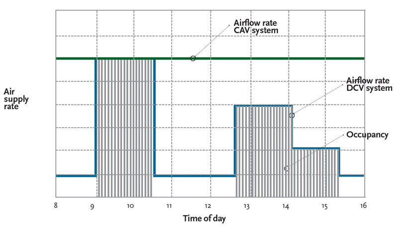
Figure 1: Applying DCV systems to control airflow rates in rooms with varying occupancy (Source: REHVA2)
The driver for demand controlled ventilation
A DCV system based on air-quality control varies the airflow rate in line with the actual internal pollution load, which is often proportional to the occupancy. Rooms in applications such as offices or schools are almost never all occupied at the same time, and it is unlikely that the peak design occupancy occurs simultaneously in those occupied rooms. Collected studies2 have shown that in cellular offices, typically less than 50% to 65% of rooms in an office block are occupied concurrently and the ‘normal’ peak may only reach 75% to 84% of all offices (these are simple occupancy and do not take into account numbers of people). Recent, ongoing Nordic work indicates surveyed cellular office rooms typically have about 50% design occupancy, and landscape offices about 75%. Average occupancy periods found in an office building range from 45% in photocopy rooms through to 33% in offices and 16% in meeting and conference rooms. Similarly, contemporary research in Scandinavian schools has shown occupancy periods in rooms of some typical Norwegian schools of four hours per day, with occupancy numbers significantly lower than design.
With a CAV system, the airflow rate is kept constant, while with a DCV system, it is modulated to meet the actual demand (as shown in Figure 1). A DCV system based on room temperature control adapts the airflow and, hence, the cooling capacity to meet the cooling load – and larger load variations will provide increased potential for energy savings.
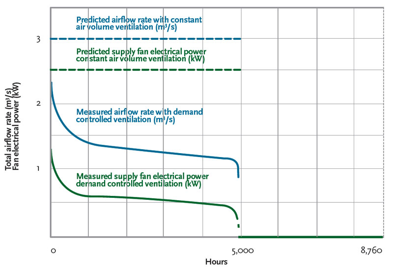
Figure 2: Measured supply airflow rates and corresponding electricity use of the supply air fan over a year for a monitored 2,500 m2 Swedish office, with 58 cellular offices and meeting rooms with a total design flowrate of 3m3/s (Source: REHVA2)
Figure 2 is based on hourly measurements during one year in an office building in Sweden. The 2,500 m2 building comprised 58 cellular offices and a number of meeting rooms. The DCV system controlled both temperature and air quality (with no water-based room units).
In this case study building, the VAV diffusers in the rooms controlled the airflow rates, both by temperature and occupancy sensors. The supply air temperature was kept constant at about 15°C. Due to the relatively low supply air temperature, individual room airflow control was particularly effective. Also, there was almost no need for additional winter heating in the air handling unit by applying heat recovery.
Interestingly, the DCV system never reached the design airflow rate of 3.0 m2/s during the measurement period. The maximum measured airflow rate was approximately 76% of the design, and there was less than 45% of the design airflow rate for 80% of the operating hours, due to the occupancy variations.
The energy saving potential of a DCV system will depend on:
• The variation in, and periods of, occupancy for the rooms;
• The minimum flow rate required and its relation to the design airflow rate of the system. This will depend, for example, on the number of rooms, the base ventilation rate in these rooms, and the minimum airflow rate possible with the airflow control devices;
• The chosen indicator for indoor air quality control. For example, if airflow rates are controlled by simple occupation sensors, the airflow rate in the room varies automatically in just two steps: minimum and maximum – average airflow rate will likely be higher with varying occupancy in the room, compared to a CO2 feed-back;
• The supply air temperature in a temperature controlled DCV system. With low supply air temperatures, the airflow pattern control in the individual rooms is more effective. VAV diffusers can manage relatively low supply air temperatures but, depending on the diffuser configuration, CAV diffusers may require higher supply air temperatures to avoid air distribution problems. Higher supply air temperatures are also required for displacement ventilation; and
• The design of the system, static pressure control strategy and dimensioning of the components.
These can have a significant impact on performance.
The estimation of occupancy patterns and load profiles presents the greatest uncertainty in predicting the potential savings.
Air supply to rooms
The airflow rate in individual rooms meets demand either by variable supply air diffusers (VAV diffusers) or by airflow control dampers (VAV dampers) in the supply duct. Minimum airflow rates are often decided by the minimum flow rates possible with the chosen airflow control device. VAV diffusers are designed to control down to relatively low airflow rates, while VAV dampers can typically control much higher maximum airflow rates, but the minimum controllable airflow rate (determined by the ‘turn down ratio’) can also be rather high, especially with larger dampers. The air should be supplied to provide a stable air movement pattern without risk of draught or stagnation, independent of the flowrate. A VAV diffuser changes its outlet configuration automatically to suit a controlled supply airflow rate, whereas in CAV, the air outlet area is constant and so could fail to deliver appropriate room air distribution at reduced flows. Since the airflow control components will, by design, provide a significant pressure drop, they should be designed, or attenuated, so that there are acceptable noise levels while supplying the required range of flowrates (this is most demanding at minimum flows). Variation in individual airflow rates will affect the static pressure in the supply ductwork, so control methods should be applied to avoid an excessive increase in pressure when the average airflow rate is low.
To operate effectively, temperature controlled DCV systems would typically have cooling supply temperatures of about 15°C to 16°C, and the supply air devices must be able to properly supply air with this relatively low air temperature. This is not particularly suitable for displacement systems, as they usually require a supply air temperature of 18°C or higher. Since in a temperature controlled DCV system the airflow rate, and the cooling capacity, is continuously adapted to the actual load, the need for extra heating in individual rooms at low occupancy is reduced compared to a CAV system, although this may not be totally removed.
Integrated ventilation and lighting control in the room, often employing the same occupancy sensor, may be used with airflow control devices from several manufacturers. Care should be taken to commission the systems to avoid nuisance cycling of lighting. However, the thoughtful scheduling of ventilation delay times, from zero up to a few minutes, can have a significant effect on the average system airflow rates.
In a DCV system based on indoor air quality control, the airflow rate is continuously adapted to the actual pollutant emissions from activities and processes in the room. It can be challenging to define the reference parameters influencing indoor air quality that the sensors must measure.
Sensing IAQ
The main indicator in HVAC systems for thermal comfort is room ‘temperature’ or sometimes a combination of simple dry bulb temperature and humidity. Air quality is defined by the composition of air in terms of gases, mainly CO2, and particulate matter (see CIBSE Journal CPD of September 2009 for further details of the parameters that influence comfort and air quality – www.cibsejournal.com/cpd/2009-09/). The airflow rate may be controlled by monitoring the room air (feed-back control), the measured/predicted load (feed-forward or predictive control), or a combination of these, to supply air to the room by some form of variable air volume (VAV) system.
The choice of an indicator or pollutant for determining indoor air quality is dependent on the possibility of measuring this parameter. There are no sensors that measure the ‘quality’ of air. Instead, surrogate gases and particles can be measured and linked to the air quality. However, in many cases, the link between the perception of air quality, the concentration levels of various substances and their influence on comfort and health is still somewhat unclear.
Carbon dioxide (CO2) is a commonly used indicator for indoor air quality in premises where people and their activities are the main pollutant source (for example, classrooms, assembly spaces, theatres, and so on) and is not suitable for spaces with low occupant density (such as apartments and houses). The rate of generation of carbon dioxide by occupants is nearly proportional to the rate of other bio-effluent generation – both are generated at the rate proportional to the number of people, their body size and their activity level. Although CO2 levels have been correlated to comfort complaints indoors, carbon dioxide does not influence the perception of air quality in the concentration levels typically found in ventilated rooms. However, the reality of accurately controlling ventilation rates might be more difficult to sustain, due to the reported variations3 in the absolute accuracy of room-mounted CO2 sensors. A US study3 indicates that there is a broad need for improvements in calibration or sensor technology for a range of wall-mounted CO2 sensors so that they can reliably meet local code requirements.
For controlling pollutants from sources other than people, the direct measurement of volatile organic compounds (VOCs) and particles may be of interest. Generally available mixed-gas sensors non-selectively measure a wide range of gases and do not indicate which gases are detected or their concentration levels. Such control regimes need to monitor both the supply and exhaust air to account for variations in pollutants in the outdoor air. Yet there is a lack of standards that describe acceptable concentrations for many common air contaminants for non-industrial buildings, and this limits the application of mixed-gas sensors for ventilation control.
An alternative way to control occupancybased pollution is to apply the presence of people as an indicator. This strategy is very often referred to as an occupancy-based DCV system, where the supply volume flowrate will be ‘feed-forward’ controlled by people entering the room, providing the exact ventilation rate per person needed to dilute the pollutants to the required levels.
Traditional occupancy sensors indicate only when the room is occupied or unoccupied, and so are suitable when the exact number of people occupying the room can be predicted, for example, in cellular offices. However, sensors that count the number of people entering/leaving a room can be used to provide greater discrimination; technologies are evolving, and they could provide the basis of a more accurate method of control than gas sensing techniques.4
The main advantage of occupancybased DCV systems is that the control and regulating equipment is much simpler than that used in gas sensor measurement and likely to require less maintenance. This is still a developing technology.
Temperature and IAQ sensor location
The sensor location is not so crucial when mixing ventilation is applied, and if a good mixing is assured, both room and duct located installations are suitable. For single zone systems, to reduce initial cost, placement in the exhaust duct is often a preferred solution. When sensors are mounted in the room, the placement should be representative of the overall occupied zone, avoiding areas of direct influence from occupants, while avoiding stagnant areas, draughts or confusing radiant sources. For example, it is suggested that in rooms where occupants are located at different heights, such as auditoria, the air quality sensor should be placed at the top of the occupied zone, while the air temperature sensors should be placed in the lower part of the room and at the top of the occupied zone. For displacement ventilation, in rooms of normal ceiling height, the air quality sensor should be located at the breathing height of seated occupants. It is recommended that temperature sensors should be located between 0.2 and 0.5 metres above floor level for rooms with wall-mounted or freestanding diffusers.
In all cases, it is important to provide ready access for maintenance and calibration.
DCV systems have the potential to provide a significant decrease in energy usage when compared to systems with a constant airflow rate, while achieving a comparable level of indoor climate. However, to realise the potential and benefit from the additional cost and complexity compared with a CAV system, careful design and rigorous maintenance procedures are required for both the mechanical and control systems.
Much of this information for this article is abstracted from the recently published REHVA publication Design of Energy Efficient Ventilation and Air-Conditioning Systems – see www.rehva.eu/en/guidebooks
© Tim Dwyer 2012
References
- ASHRAE International Climate Zone Definitions, ASHRAE, www.ashrae.org/File%20Library/docLib/Public/20081111_cztables.pdf
- Design of Energy Efficient Ventilation and Air-Conditioning Systems, REHVA, 2012, www.rehva.eu/en/guidebooks p57.
- Fisk et al., CO2 Monitoring for Demand Controlled Ventilation In Commercial Buildings, LBNL, 2010, www.demandcontrolledventilation.lbl.gov/accuracy.html
- Fisk and Sullivan, Optical People Counting for Demand Controlled Ventilation: A Pilot Study of Counter Performance, LBNL, 2009