
As fire dampers are hidden from building occupants, and potentially also from the building owner and operational team, their essential role in maintaining protection against the spread of smoke and fire may only become obvious if a property suffers one of the 50 fires that occur daily in nondomestic UK buildings.1
Fire dampers are installed to prevent the spread of fire where air ducts penetrate fire resistant barriers. Typically, smoke dampers are designed to prevent the flow of smoke and products of combustion (and are able to withstand high differential pressures); these are operated by thermally-tripped actuators from smoke detectors in the ductwork or via a centralised fire detection system. Fire and smoke (or fire and leakage rated) dampers combine both functions. For the majority of escape routes and sleeping areas, the fire dampers must also be operated by a smoke detector or suitable fire detection system.2
The evolution of harmonised standards
The Construction Products Regulation (CPR) aims to harmonise conditions across Europe for the marketing of construction products – identifi ed by the use of the ‘CE’ mark. This mark3 is to promote free trade and remove technical barriers by unifying the recognition of products with ‘European conformity’. This ensures that a product meets essential harmonised requirements of the applicable EC directives, but it is not, in itself, aimed at improving standards, nor does it imply that the product is made in Europe.
Prior to 1997, the only available UK standard for assessing the performance of fire dampers was BS 476 20-22:1987 – Fire tests on building materials and structures. As its name suggests, this standard was principally designed for static construction components, and so did not include the breadth of testing that could fully assess the tolerances, fit and dynamics that are intrinsically associated with the performance of a mechanical fire damper. The subsequent development of the ‘testing’ standard BS EN 1366 – Fire resistance tests for service installations, provided a set of standardised tests that were relevant to the practicalities of application of fire and fire/smoke dampers.
From 1 July 2013, it will be a requirement for all new fire and smoke control dampers used in UK buildings to be CE-marked to indicate compliance with the relevant ‘product’ standard (see Table 1). These product standards provide recognised criteria covering their integration into the building structure, referring to the ‘testing’ standard BS EN 1366, and unlike the previously employed BS 476 procedures, this standard contains test procedures that are attempting to ensure dampers are installed in ways that are clearly consistent with the regulated and tested installation detail.
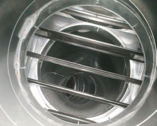
Figure 1: Multi-blade fire damper installed in a circular duct (Source: Ruskin Air Management)
Main types of fire dampers
There are three principal types of fire dampers:
Curtain fire dampers are normally a series of interlocking blades, which fold to the top and are held open by means of a thermal release mechanism (that may be electrically actioned) that activates at around 72°C.
Intumescent fire dampers incorporate components that expand when heated by a fire, activating typically in the range 120°C to 270°C. Some incorporate an electromechanical device to provide cold smoke containment through an external control.
Single and multi-blade fire dampers have one or more linked framed pivoting blades, released by a thermal release mechanism (that may be electrically actioned) at around 72°C.

Table 1: Principal European standards regulating fire dampers
Fire damper testing
Figure 2 shows a simplified layout for a BS EN 1366 test that, in this case, is designed to assess the ability of a fire damper to withstand heat and prevent the passage of smoke and gases at high temperatures in a horizontal duct. The damper is installed into the furnace wall and a plenum is fixed to the face of the damper, leading to a fan that maintains a set subatmospheric pressure on the face of the damper during the test. The damper is opened and closed 50 times (based on two maintenance checks per year, nominally simulating 25 years’ service), prior to the fans or fire being started to test mechanical robustness and then left in an open position at the start of the fire sequence. If a leakage test is to be undertaken, the damper is closed and the leakage rate measured using the measuring system in the test duct at ambient conditions prior to the fire test. The damper is then set to a position to give a velocity of 0.15 m/s across the face of the damper, the furnace is started, and the damper blades must fully close automatically within two minutes. The damper is then subjected to a required subatmospheric pressure and temperature of 1,050°C to 1,150°C for two to four hours.
Leakage (S) is leakage during the fire test of less than 200 m3 h-1 per m2 of damper face area, measured at ambient temperature.
This is the same requirement for all sizes of manufactured dampers, and so can be particularly demanding for a range with small size dampers.
Integrity (E) is the time that a damper allows a leakage less than 360 m3 h-1 per m2 without a failure. This would normally be associated with smoke dampers and the fire performance of a fire and smoke damper.
Insulation (I) is the average temperature rise on the unexposed face to 140°C, with a maximum point value of 180°C.
The rating will reflect the performance of the damper – for example, ES 240 would indicate a damper that has been tested for both integrity and leakage and has maintained performance to standard requirements for four hours. (Historically, the UK has used the format ‘ES 240’, but under EN 13501 this will be shown as ‘E240S’.)
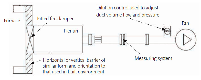
Figure 2: A simplified representation of the setup for testing fire dampers to BS EN 1366
System design
System design and installation for fire and smoke dampers must be project-specific, taking into account up-to-date legislation and manufacturers’ recommendations.
So while it is important to ensure that appropriately certified dampers are used, it is as critical to install those dampers so that they reflect the conditions in which they were tested and assured. This requires close liaison between manufacturer, designer and site workers. Consideration must be given not only to damper installation, but also to access for maintenance and testing during the lifetime of the building.
The key tasks for successful fire protection in a building, as identified by DW/145, are:
Fire/smoke compartmentation – A fire strategy should be established and recorded that clearly shows fire and smoke compartmentation and the details of the protected areas.
System specification and design – Those responsible must ensure that the design and application is suitable for the particular project and not simply generic.
Programme of activity – This includes the relationship with other trades, and the physical position of the damper in relation to the building fabric and other services.
Damper procurement – All the appropriate specifications for dampers must be supplied by the designer. Substitutions for dampers other than those specified require checking by the designer.
Damper supply – Dampers must be supplied with dimensionally detailed guidance on how the damper assembly is to be installed and evidence that the method has been appropriately fire tested.
Fire separating elements/barriers – A responsible person must ensure that fabric, including fire barriers, have appropriate penetrations formed to accommodate dampers, in accordance with tested specifi cations.
Penetration seals – Any seal that is applied around the damper should be in accordance with tested specifi cations, and the installer must be clearly aware of the required standard of work.
Compliance with Building Regulations – Building control authorities must be satisfi ed that the design shows compliance with Building Regulations. The methods of installation must have been successfully fire tested by an independent body on behalf of the damper manufacturer.
Managing the installation process
The Building and Engineering Services Association’s (B&ES) DW/145 Guide to Good Practice for the Installation of Fire and Smoke Dampers highlights the role of the CDM (construction, design and management) coordinator (as required by the 2007 CDM regulations) and the principal contractor, who have key roles in the planning and management required to assure a coherent and compliant installation. Resources such as the BSRIA Design Framework4 may be employed to help schedule the designated responsibilities of, and actions for, individuals. The CDM coordinator will clearly identify specifi c responsibilities for appropriately competent members of the team, which may include, for example, project manager, building control, fire consultant, damper manufacturer and installation contractor.
Specifi cally, for successful damper installation, the principal criteria are:
• Installation should meet design specifi cation;
• Dampers must be installed in accordance with tested methods; and
• Dampers should be fi xed either directly in, or immediately adjacent to, the fire barrier and must be supported independently of the duct work.
By meeting these criteria, untested adhoc installations will be eliminated.
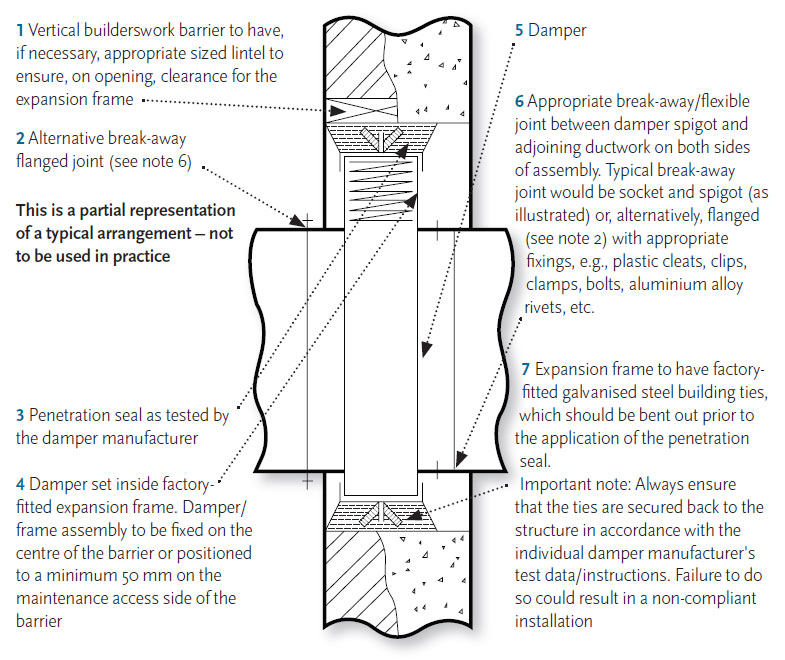
Figure 3: Partial extract of fi re damper installation detail (Source: DW/145)
Specifying an assured installation
DW/145 provides a list of technical information that the system designer should provide to the damper installation company. This includes:
• Manufacturers’ test data sheets and dimensions with detailed technical illustrations;
• Performance characteristics and associated controls specifi cation;
• Materials’ specifi cation and critical dimensions;
• Project-specifi c detail including relationship of damper with fire barrier, connection to ductwork, damper supports, and expansion arrangements around damper. This would include detailed fi tted drawings, such as the example in Figure 3 (note that this is an incomplete extract of a example full drawing from DW/145);
• Overall system design drawings, with cross-reference numbering system identifying dampers; and
• Programme identifying installation sequence, installation and hand over (DW/145 has indicative programmes).
Practically, there will be issues on site that require some deviation from the expected design detail. Although the whole team have responsibility, any variations are likely to require approval of building control and/or the local fire authority. Damper manufacturers are not empowered to provide that approval. Requesting approval after the event is not acceptable.
To ensure a smooth transition, the whole team must complete a list of information at the handover – DW/145 provides generic checklists that can be used as the basis for this. The completed checklist is likely to form part of the legislative requirements in the future, as part of the evidence trail that appropriate processes have not only been followed, but also properly monitored. The building owner/operator has responsibility for continuing fire safety, and requires handover information for both the initial installation and commissioning details, to allow future testing and inspection.
Although out of sight, fire and smoke dampers cannot be out of mind.
© Tim Dwyer 2012
Further reading:
- DW/145 – Guide to Good Practice for the Installation of Fire and Smoke Dampers, B&ES, 2010.
- BRE Good Building Guide 81 – Installing fire resisting ductwork and dampers, BRE 2011.
- Disjointed Approach – CIBSE Journal, September 2011 p55-57
Thanks to Kevin Munson at Ruskin for assistance with this article.
References:
- Fire Statistics, Great Britain, 2010 – 2011, DCLG, November 2011, p44.
- The Building Regulations (England & Wales) 2000, Approved Document B – Fire safety (2006 rev 2007 & 2010), Vols 1 & 2. DCLG.
- www.ec.europa.eu/CEmarking.
- BSRIA BG6/2009 Design framework for building