
The recently published annual progress report1 by the UK government’s Committee on Climate Change (CCC) indicated that significant improvement was needed in the take up of energy saving measures to meet the UK’s CO2 emission reduction targets, particularly as there are practical limits on applying fabric improvements to existing buildings. This CPD will provide a brief update on the provisions that are driving this improvement and consider how one technology – condensing continuous flow hot water heating – can help to achieve a relatively small but significant reduction in CO2 emissions.
The European Union (EU) is rolling out legislation2 to ensure that end users are more properly informed about the potential environmental impact of many appliances, including hot water heaters. According to the background research undertaken by the EU, it is thought that the continued strong sales of low-efficiency water heaters is due to end-users considering the purchase costs of products rather than their life cycle costs, since the information available to purchasers on the energy efficiency of water heaters is limited. This lack of knowledge, combined with potentially weak standards, can lead to the developers of an installation providing equipment that requires lower capital outlay but at higher life-cycle energy (and environmental) costs – a particular risk with tenanted properties. This situation is seen as especially challenging when water heaters are linked in as part of a solar-led system, resulting in end users missing opportunities for cost-effective improvements in energy efficiency.
There have been a number of legislative processes and white papers published by the UK government since the landmark 2004 Energy Act that, in various – and possibly disparate – ways, attempt to direct future energy use in buildings to reduce CO2 impact. Just last December, the government3 confirmed that heating and powering buildings still produced 35% of the UK’s ‘greenhouse gas’ emissions. An aspiration of that report was that by 2050 ‘emissions from heating and powering our buildings will be virtually zero’. The expectation is that the energy supply will be ‘decarbonised’ by reducing the UK’s dependence on traditional fossil fuels. In the meantime, improvements in the effectiveness of the building envelope and the efficiency of its environmental systems are in the forefront of carbon reduction measures.
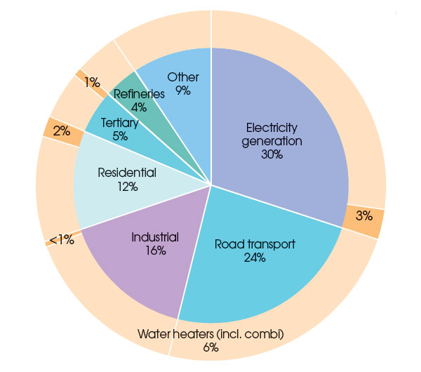
Figure 1: EU-15 energy-related greenhouse gas (GHG) emissions (more than 80% of total GHG emissions) by sector, according to EEA 2007
Data collected in 20054 indicated that water heating (both gas and oil fired) emits 6% of all fuel-related CO2 in the EU (as shown in Figure 1). This EU study considered opportunities to reduce the carbon resulting from water heating, and suggested that even applying a reasonably conservative ‘realistic’ outlook for improving the efficiencies of hot water production, 71Mt CO2 equivalent per annum across Europe might be saved compared with ‘business as usual’. The report proposed that such a scenario would require:
Financial incentives – The recent CCC report indicated that the 2010 boiler scrappage scheme was responsible for an increase in replacement rates for boilers. Under certain restricted circumstances, the Green Deal may provide opportunities for funding replacement hot water heaters;
Certification – Such as building energy performance certificates (EPCs) or display energy certificates (DECs);
Labelling – Such as that resulting from the proposed rollout of labels to meet the EU energy efficiency labelling directive5 (as illustrated in Figure 2). The proposed energy labels are for stand-alone water heaters and hot water storage tanks, as well as for combined packages of water heaters and solar thermal systems; and
Minimum targets – Set through such devices such as the UK Building Regulations. For example, the current consultation document6 for the 2013 revision to AD Part L has a proposed recommended minimum gross efficiency for direct gas fired hot water systems of 90% for new construction over 30kW, compared with the previously recommended minimum of 73%. A comparable mandate in 2005 that practically demanded all new domestic boilers be condensing – despite scepticism at the time about their practicality7 – led to more than nine million installations8.
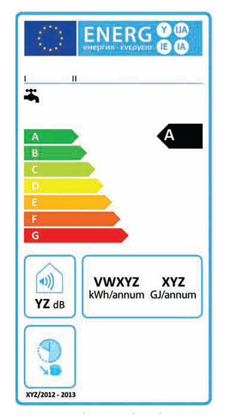
Figure 2: Proposed conventional water heater EU energy label. Practically, to achieve an ‘A’ rating, anything but small domestic hot water heaters will have to be condensing water heaters
The latent potential gain in efficiency
There is a mature UK market in high efficiency dedicated direct gas-fired water heaters, having been applied in the UK for more than 40 years. The gas market in the UK and Europe is principally natural gas (that is, approximately 90% methane (CH4) – a hydrocarbon); natural gas has a high latent heat content (water vapour) in the products of combustion. The actual composition of natural gas will vary, depending on its source.
The combustion of hydrocarbons in a water heater is a reaction of oxygen (O2) in the air (air principally being comprised of 79% nitrogen and 21% oxygen), with the carbon (C) and hydrogen (H) compounds in the fuel creating CO2 and superheated water vapour (H2O), plus the nitrogen mainly passing straight through. A simplified combustion equation for the most effective combustion of methane (given in ‘moles’) is
methane + air => water + carbon dioxide + nitrogen
CH4 + 2 (O2 + 3.76N2) => 2H2O + CO2 + 7.52N2
with the flue gas (on the right hand sides of the expressions above) containing neither fuel nor oxygen, both having been completely utilised in the chemical reaction. This perfect ratio is called the stoichiometric ratio, and provides a theoretical best mixture for combustion of the methane gas to produce heat without wasting fuel or causing excessive harmful gases.
The relationship established by ‘Avogadro’s principle’ means that each mole of gas will take up the same volume, and so whilst the water is in a vapour form (and the flue gas being known as ‘wet’):
1 volume CH4 + 2 volumes O2 + 7.52 volumes N2 => 2 volumes H2O + 1 volume CO2 + 7.52 volumes N2
So the stoichiometric air-to-fuel volume ratio for methane combustion is 9.52 (air) : 1 (methane).
The percentages in this stoichiometric mixture’s 10.52 volumes of flue gas are 9.5% CO2, 71.5% N2, and 19% H2O that will be in vapour form and will include significant amounts of latent heat. (The instrumentation used to control the air/gas mixture is likely to monitor the ‘dry’ flue gas that has a total of 8.52 volumes and a resulting 11.74% CO2 by volume, under stoichiometric conditions.)
All combustion systems use slightly more air than theoretically needed to ensure complete combustion of the fuel (known as ‘excess air’) – this is represented by a lambda value, λ, of greater than 1, where λ = (actual air ratio)/(stoichiometric ratio). If systems were operated with a lambda of 1, it is unlikely that all the gas would react – due to imperfect mixing, as well as variations due to pressures and air moisture content – so wasting fuel. Incomplete combustion will also create poisonous carbon monoxide (CO) and particulate matter (soot) in the flue gas.
A simplified example process with 20% excess air would be:
CH4 + 2.4 (O2 + 3.76N2) => 2H2O + CO2 + 0.4O2 + 9.02N2 and λ = (actual air ratio)/(stoichiometric ratio) = 10.02/9.52 = 1.05
However, the increased air supply will reduce the temperature of the flue gases (so reducing efficiencies) and potentially increase the amounts of environmentally significant oxides of nitrogen (NOx). By carefully monitoring the flue gas composition, the excess air levels can be controlled at the lowest possible level, so that the oxygen concentrations in the high temperature zone of the combustion process can be minimized to reduce the NOx formation and maintain efficiencies.
Recovering latent heat to improvehot water heating efficiencies
The application of dedicated water heaters has become common in small commercial and industrial applications. The development over the last 15 years of non-storage, high output ‘instantaneous’ continuous flow heaters allows the provision of large quantities of potable (domestic) hot water without the need to store hot water. If well designed, controlled and operated, such a (non-condensing) heater can provide gross efficiencies of more than 80%. Such systems can also provide operational and space advantages by not requiring storage; storing hot water will add to heat losses, and the additional pipework and controls add to the complexity of systems, both in design and maintenance, resulting in lower gross system efficiencies than for non-storage, continuous flow systems. However, they need to be sized to cope instantaneously with peak demand, whereas storage systems can spread the fuel demand over a longer period.
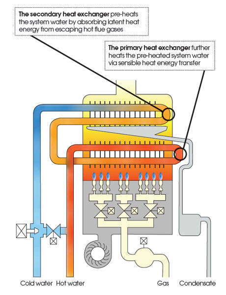
Figure 3: An example of a condensing water heater
A condensing continuous flow hot water heater additionally attempts to recover the heat in the flue gases through the flue by deliberately inducing condensation (recovering the latent heat in the flue gas). This is achieved by adding a ‘secondary’, or extended, heat exchanger in the flue that exchanges heat with the incoming water, as shown in the example in Figure 3. The dew point of the flue gas from the combustion of natural gas is around 57°C; hence, condensing systems operate most efficiently with incoming water temperatures below 57°C. Condensation will potentially release approximately 3.5MJ per m3 natural gas and increase overall gross efficiencies to more than 90%. Since the resulting condensate is slightly acidic (typical pH 3.6 – similar to orange juice), the materials for the heat exchanger are frequently manufactured from stainless steel. All the materials and construction that is exposed to the condensate must be able to properly resist the acidic atmosphere.
The additional performance of a condensing water heater is due not only to the recovery of latent heat, but also to the lowering of the flue gas exit temperatures. As the flue gas exit temperature falls, there will also be greater amounts of condensation – hence, again, increasing the overall efficiency. The resulting flue gases are typically 50-60°C and, depending on the external conditions, can result in considerable pluming from the flue as the remaining water vapour in the flue gas condenses into small entrained liquid droplets.
The low flue gas temperature is likely to mean that a fan is needed to remove products of combustion – this would be an integral part of the condensing water heater. By applying fast response digital control to the fan – using sensors in the flue gas to monitor the excess air – it can be automatically regulated to provide close to stoichiometric combustion, while ensuring that the flue gases are safely removed through the positively pressurised flue.
Since the flue will be subjected to low temperatures, it may be made from plastic, stainless steel, ceramic or glass – the key quality being its resistance to the slightly acidic flue gases. A fan-assisted flue will also provide greater flexibility for the positioning of the system (i.e., it does not need to be sited adjacent to an external surface), as well as having a small diameter, allowing simpler routing through the building; significant lengths of PVC or ABS pipework (more regularly associated with drainage applications) can be used. A drain is required to remove the condensate and, again due to the low condensate temperatures, this can be run in plastic (though in a position that is not at risk of freezing). It is important that the condensate drains freely from the heat exchanger, as any residual liquid will reduce the heat transfer and potentially increase the acidity adjacent to the heat transfer surfaces.
When a condensing continuous flow water heater system is constantly fed with water from the mains supply – typically under 10°C and well below the required 57°C – it will work in condensing mode throughout the whole year. However, there are many applications where the feed water may have a higher temperature – for example, in larger systems where there is a requirement to provide circulation in the hot water system, or in systems that are providing instantaneous top-up to water pre-heated via a renewable heat source (such as solar thermal or heat pumps). These systems will still condense if the feed water is below 57°C; however, it is important that the selected heater is designed to accept such pre-heated water.

Figure 4: A commercial continuous flow condensing hot water heater
Conclusion
The challenge of continuing to reduce carbon emissions from buildings will by improving the building fabric become more complex to implement. The decarbonisation of the energy supply is still some 40 years (at least) in the future and, hence, the benefits of using lower carbon systems are increasingly important. More than 9%8 of energy consumed in non-domestic UK buildings is by gas water heating and, compared to traditional oil, gas and electric powered storage systems, the application of condensing continuous flow water heaters (as shown in Figure 4) can reduce the energy required to supply hot-water, and so reduce operational CO2 emissions.
© Tim Dwyer 2012
References:
There are several documents and websites (most freely available) that provide guidance on the management processes and technical solutions:
- Meeting Carbon Budgets – 2012 Progress Report to Parliament, Committee on Climate Change, June 2012.
- Directive 2009/125/EC of the European Parliament and of the Council of 21 October 2009, establishing a framework for the setting of ecodesign requirements for energy-related products.
- The Carbon Plan: Delivering our low carbon future – Department of Energy and Climate Change (DECC), December 2011.
- Eco-design water heaters, September 2007, www.ecohotwater.org
- Directive 2010/30/EU of the European Parliament on the indication by labelling and standard product information of the consumption of energy and other resources by energy-related products, 19 May 2010.
- 2012 consultation on changes to the Building Regulations in England – Section two – Part L (Conservation of fuel and power). Proposed changes to technical guidance, DECC, January 2012.
- http://www.guardian.co.uk/money/2005/apr/02/consumerissues.jobsandmoney accessed 11 July 2012.
- The Future of Heating: A strategic framework for low carbon heat in the UK, DECC, 2012.