At the recent CIBSE ASHRAE Technical Symposium, ‘power factor’ correction was raised in a plenary session, and it was clear that there was some uncertainty about some of the concepts being discussed.
This CPD article aims to provide an introduction to the principles of power factor, and some wider issues of power quality on buildings.
Electrical systems supply power to equipment incorporating magnetising actions – such as many motors driving fans, pumps and compressors, and certain types of lighting – will require additional current above that needed to do useful work; this current is used to produce the magnetic flux in the device. In addition, the basis for calculating electrical loads is based on the concept of ‘linear’ loads, which means that they draw a sinusoidal current wave-shape to match the supply voltage. However, increasingly there are a numbers of non-linear loads in buildings that will also de-rate the performance of the distribution network by adding harmonics into the supply system (due to their pulsing actions) potentially affecting the performance and longevity of equipment.
This reduction in power quality does not necessarily cost the consumer money directly, but for commercial and industrial users it may well affect the electrical tariff costs, and will alter the effective capacity of the electrical distribution system.
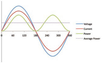
Figure 1: Voltages and current in a purely resistive system
Load types
In an alternating current (AC) electrical system there are resistive, inductive and capacitive components.
Resistive loads include incandescent lamps, resistance heaters and the cable itself. If a circuit were purely resistive, the current and the voltage would be in phase.
A representation of the voltage and current waveforms for a resistive system is shown in Figure 1. No real power system is purely resistive, as it will certainly also have some capacitive characteristics (the ability to store energy briefly).
Inductive loads would typically include induction motors, the ballast coils used with fluorescent lamps, many low energy lamps, and any systems that include magnetic components – such as transformers, welding equipment, and many electrical goods. In an inductive circuit, the current will ‘lag’ the voltage waveform, as shown in Figure 2.
Capacitive loads include such components as digital electronic equipment – a load that is becoming increasingly prevalent in commercial buildings. In a capacitive circuit, the current will ‘lead’ the voltage waveform.
Capacitive loads (in the form of capacitors) are added to systems as a means of counteracting inductive loads.
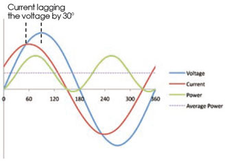
Figure 2: Voltages and current in a simple inductive system with a lag of 30° (and a resulting displacement power factor of cos30° = 0.87)
Most commercial and industrial buildings are likely to have an overall load profile that is inductive. Both inductive and capacitive loads are known as ‘reactive loads’ and, preferably, the goal should be to have almost zero reactive currents (meaning that the current and voltage are in phase) at the point that the electrical supply enters the building.
Inductive loads require a current to create a magnetic field (flux), and this field enables the device to produce the desired work. The inductive circuit cyclically absorbs energy from the system (during the build-up of the magnetic field) and then re-injects that energy back into the system (during the collapse of the magnetic field). Hence the current (I) in the supply and distribution system will increase (with the additional inductive current), and so the losses in cables and transformers will rise – frequently referred to as ‘I2R losses’ (R being the electrical resistance).
This reactive power is also known as ‘wattless’ power. It does not directly affect the useful power (watts) drawn by the appliance to produce the work, heat or light. However, the total demand on the power supply systems, measured in VA (volts x amps), and the magnitude of the flow of energy in the conductors, will increase to provide the reactive power. The total or apparent power (kVA) required by a reactive system is the sum of the ‘true’ or ‘real power’ (kW) and the reactive power (kVAR), commonly known as ‘kilovars’.
The power factor is the ratio of the real power (kW) to the total (apparent) power (kVA).
The lag (or lead) angle can be shown using a phasor diagram (Figure 3) and simple calculations used to determine unknown values. The cosine of the angle f is the ‘displacement power factor’ (normally simplified to just ‘power factor’).
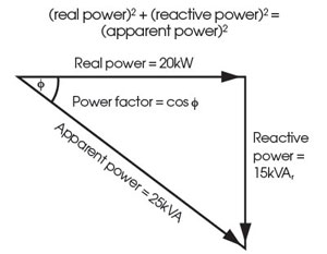
Figure 3: Phasor representation of power (with example values taken from the uncorrected example motor described in the text)
So, for example, a particular 20kW motor operates at a power factor of 0.80 (lagging). Hence, the apparent power required by the motor = 20kW/0.80 = 25kVA. If the power factor is improved to 0.95, then the corrected apparent power = 20kW/0.95 = 21kVA. In this example, the apparent power is reduced by 16% – this will not necessarily reduce energy bills, but may contribute to having smaller cables or improved tariffs.
In commercial and industrial buildings, a power factor of below 0.9 is considered to cause excessive running currents, and is often penalised through electricity supply tariffs by incurring a financial charge for reactive power (kVAr) that goes above a set proportion of the real power (kW). So, typically, a building’s power factor would be maintained at 0.95 or above by the installation of ‘power factor correction’ (PFC).
The motor from the previous example can be simplified into a resistance, R, and inductance, L, as shown in Figure 4a. When voltage is applied to the circuit, the main supply will need to provide both I2, the ‘inductive’ current, and I3, the ‘resistive’ current.
If, subsequently, the switch is closed, as in Figure 4b, the capacitor is instantly charged and this charge oscillates between the capacitor and inductor, creating a current through C and L. The oscillating charge provides the ‘extra current’ in I2 and the current from the main supply is reduced. This is known as static power factor correction, and is often used with individual pieces of equipment. It may not be physically practical or financially economical where there are a large number of devices requiring power factor correction.
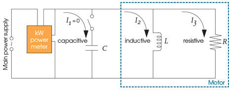
Figure 4a
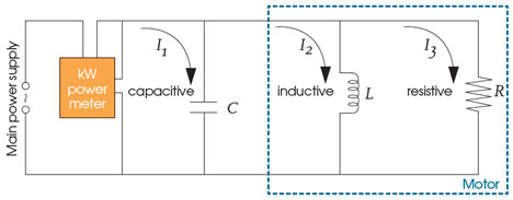
Figure 4b
Figures 4a and 4b: Adding a capacitor as a means of correcting the power factor (after1)
These correcting capacitors can be of a fixed rating to match the inductive load of a large item of equipment, or be in a bank of capacitors, mounted close to significant loads or at the building power intake switchgear. If centralised, these are likely be progressively brought into circuit by automatic controls to match inductive loads in the building.
Power factor is unlikely to be a constant. For example, motor inductance will alter with motor speed (as shown in Figure 6). This may well demand more complex solutions, as inappropriate ‘balancing’ capacitance can add to the harmonic problems discussed below, or simply add unwanted reactance.
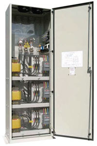
Figure 5: Centralised power quality correction automatically adjusts to meet the needs of the building electrical load
So induction motors, whether driving a fan, pump or lift, should be sized appropriately to meet the design requirements, otherwise they will always run at a lower power factor (and efficiency). Variable voltage AC drives and DC static converter drives have such a wide range of power factor over the speed and load range that it is very difficult to provide power factor correction to maintain values of 0.9.
For large motor loads – such as those used in lifts – variable voltage, variable frequency drives provide better all-round drive performance than variable voltage control alone, and give near unity power factor operation. (Static power factor correction must not be applied at the output of a variable speed drive, solid state soft starter or an inverter, as it will damage the electronics.) Some systems use multiple motors so that they can collectively operate with individual higher power factors (and efficiencies).3
Discharge lamps require a ballast to start and control the lamp and, if provided by traditional wire-wound coil ballasts, need some power factor correction. LED and some compact fluorescent lamps can have power factors significantly less than 14 and will normally be corrected locally within the luminaire. High-frequency electronic ballasts are available for a wide range of fluorescent and compact lamps, providing a power factor of 0.95.5
Power factor correction can be implemented using fixed capacitors or automatic variable power factor units. By installing the equipment close to the load, the kVAr load on the supply cable is reduced, thereby possibly allowing a smaller distribution cable to be used.
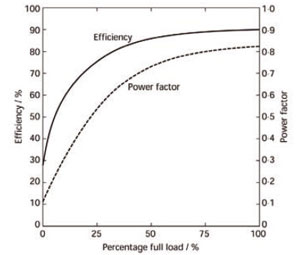
Figure 6: The variation of power factor with induction motor speed2
Harmonics
Modern power systems are increasingly affected by harmonic distortion. ‘Non-linear’ loads – such as computers, inverters (for speed controllers), electronic power supplies and discharge lighting – can affect the supply waveform. They ‘switch’ on and off very quickly, making step changes to the current and so creating harmonics in the electrical supply system. As illustrated in Figure 7, the harmonic components cause the (normally sinusoidal) waveform to be distorted. This will detract from the quality of the powersupply and increase the ‘wattless’ current in the system – wattless, in this case, since the harmonic current has no matching voltage harmonic to produce useful power. This can cause excessive heating in motors, abnormally high current levels through system capacitors, voltage peaking and unexpected tripping, and may also affect the measurement accuracy of monitoring devices.6
The harmonic components cause greatly increased eddy current losses in transformers. These losses are proportional to the square of the frequency, so with the higher frequency harmonics, the operating temperature of the transformer will increase and equipment lifetime is shortened. Even moderately loaded transformers supplying IT loads will have much lower lifetimes than expected, unless proper precautions are taken.8
‘Passive’ harmonic filters may be used to reduce the harmonic current so that the nonlinear device appears to the system to react in a way that is similar to a simpler linear load.
The power factor can then be adjusted, using capacitors or inductors as required. So called ‘detuned’ capacitors may be used – these are a matched reactance/capacitance applied to ‘dampen’ the system harmonics at particular frequencies as well as providing power factor correction.
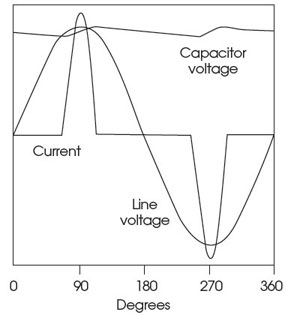
Figure 7: The current drawn by an uncorrected electronic power supply (note that EU regulations require computer power supplies to incorporate measures to reduce this effect on the mains supply)7
More flexible (and expensive) ‘active power factor correctors’ are also used to alter the waveform of the current drawn by a load to improve its overall power factor.
Under EU regulations, power supplies (such as those used in modern desktop computers) are required to have appropriate filters to minimise the adverse effects on the power supply systems.
Benefits of power quality correction
This article has provided a very brief introduction to the area of power quality in buildings. However an awareness of the issues may provide the basis for further discussions to improve systems that:
- Reduce/eliminate network utility charges related to reactive power;
- Reduced loads on power distribution systems;
- Improve the overall performance of the power system that can increase equipment longevity; and
- Provide greater stability through the reduction/elimination of harmonics.
© Tim Dwyer 2012
Further reading:
CIBSE Guide K – Electricity in buildings provides an excellent resource covering the main areas of electrical application in building services.
Power Quality Self-assessment Guide (and associated Leonardo Project Power Quality Application Guide documents) available as a free download from www.leonardo-energy.org provides detailed discussion of this area.
• Thanks to Les Norman at London South Bank University for his input to this CPD module.
References
- Misakian, M. et al, Regarding Electric Energy Savings, Power Factors, and Carbon Footprints: A Primer, NIST Technical Note 1654, October 2009.
- CIBSE Guide K, Electricity in buildings, CIBSE 2005.
- CIBSE Guide D, Transportation systems in buildings, CIBSE 2010.
- BRE 15/10 Specifying LED lighting, BRE 2010.
- CIBSE Guide F, Energy efficiency in buildings, CIBSE 2004.
- Chapman, D., Power Quality Application Guide, European Copper Institute and Copper Development Association, 2001 (EU Leonardo Project).
- Fortenbery and Koomey, Assessment of the Impacts of Power Factor Correction in Computer Power Supplies on Commercial Building Line Losses, California Energy Commission, 2006.
- Chapman, D., The Cost of Poor Power Quality, European Copper Institute and Copper Development Association, 2001 (EU Leonardo Project).