Inappropriate design or lack of care in operation when assessing the pressurisation of closed water distribution systems can lead to consequential problems from the accumulation of air in the system. If not properly removed this can cause serious difficulties with water circulation as well as increasing corrosion in ferrous pipework systems and so build up particles (‘magnetite’) within the pipework system. This can lead to the unnecessary use of chemicals to ‘treat’ the water.
Building up the pressure
The flow of water in a pipe system can be related to the ‘Bernoulli Equation’ (just as with air flow in the August CPD article) and this can be expressed in terms of the ‘static head’ at any point in a piped system. And when referring to the flow of liquids the term ‘head’ is frequently used in place of ‘static head’. To evaluate the ‘head’ of water that corresponds to a particular pressure, the head = P/ρ g , where P is the pressure in Pascals, ρ is the density of the liquid, and g is the acceleration due to gravity, 9.81 m/s2 (The head is a ‘gauge’ pressure, ie relative to atmospheric pressure).
So considering 2 points in a closed pipework system using the Bernoulli Equation with the water flowing from point A to point B:-
Static head A + Velocity Head A + Potential Head A =
Static head B + Velocity Head B + Potential Head B + frictional losses A to B
PA/ρg + cA 2/2g + zA = PB/ρg + cB 2/2g + zB + (frictional loss)
Where c = water velocity (m/s), z = height of pipe above datum (m)
When undertaking pipe sizing and pressure loss calculations (for example to select a circulation pump or to assess the system pressure profile) the pressure drop as the water flows through the system may be evaluated using standard tables and charts. (CIBSE Guide C 2007 provides pressure drop data in a simple spreadsheet unlike previous editions that had numerous printed tables). Typical design pressure drops in water systems for commercial and domestic piped systems are in the order of 300Pa/m pipework (or 0.03m head loss per metre) and water velocities range from less than 1 m/s (for small domestic systems) to 3 m/s for pipework 50mm or greater in diameter1. (Note: these are based on traditional accepted norms for noise, pressure drop and economic pipe size, although certainly not hard absolute rules).
Additionally there will be pressure drops in fittings and components. When analysing the pressure in a water system the velocity head is often ignored as its changes are comparatively small compared to the changes that take place in both static head and potential head.
The pressure’s on
Considering a simplified system all on one level (ie height ‘z’ is constant) the potential head will be constant and, until the water flows, the system static pressure is the same throughout (at around atmospheric pressure, or zero metres head). When the circulating pump is switched on and water flows there will be losses in static head (due to friction) around the system related to the water flow rate and temperature and the pipe size and its roughness. The pump will be selected to provide the design flowrate against the accumulated system pressure losses. Figure 1 shows a simplified system with the pump in operation. The resulting static pressure is shown diagrammatically in Figure 1 by the dotted green line – positive static pressure (relative to atmospheric) is above the grey pipe line and negative below the grey line.
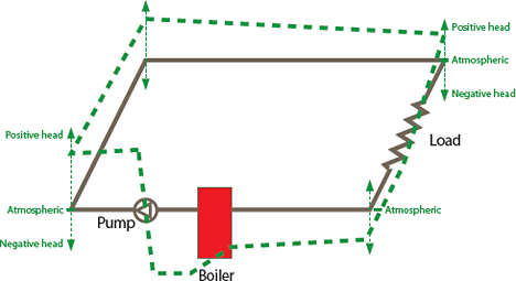
Figure 1: Static pressure (or head) around a system all on one level (height ‘z’ is the same all round)
Expanding the subject
But the simplified system in Figure 1 is missing a key element. The density of water reduces and hence its specific volume rises as temperature rises and unless there was a provision to absorb the additional volume there could be serious consequences. For example, if water is heated from 4°C to 80°C the density falls from 1000 kg/m3 to 971.8 kg/m3, and so the specific volume rises from 0.001 m3/kg to 0.001029 m3/kg – an increase in the water volume of 2.9%. So, if the system in Figure 1 was 100 metres of 50mm nominal diameter medium steel pipe this expansion would add about 6.6 litres to the volume of the water contained in this pipe. Traditionally an open tank (or cistern) provided an opportunity for the water to expand and then return into the system when the system was cooler (the cistern would also supply make up water when, for example, it leaked from the system).
As shown in Figure 2 the cistern also has an important role in pressurising the system – providing a head equal to the height of the tank above point N, known as the ‘Neutral Point’. When the system is at rest the static head will be the same throughout the whole system. For example, if the tank was 6m above point N, the static pressure, ρ g z = 1000 x 9.81 x 6 = 59 kPa or approximately 0.6bar. The static head at point N will remain practically constant irrespective of pump size or speed and there will be only small changes with water temperature.
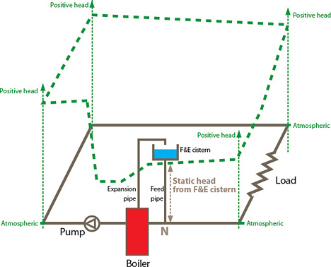
Figure 2: Simplified system with feed and expansion cistern
By appropriately pressurising the system (by having point N close to the pump suction) all of the pipework will remain at a positive pressure whilst the system is operating (as shown by the position of the dotted pressure lines in Figure 2). Positive pressure is beneficial as it prevents drawing air into the system (through micro gaps in fittings); it reduces the opportunity for dissolved air to be released from the water and collecting as free air within the pipework; and it allows the system to operate with less chance of the water locally vaporising or ‘cavitating’.
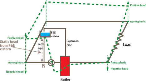
Figure 3: Moving the Neutral Point to an inappropriate position
The position for point N can be altered by connecting the cistern at an alternative point (such as in Figure 3) however if this is on the downstream side of the pump (closer to the pump discharge than the suction) it will not provide the same benefits as part of the system will have a static pressure below atmospheric pressure.
This is likely to manifest itself in more free air in the system, potentially causing:
- air locks;
- problems with commissioning systems (such as unreliable pressure readings);
- production of ‘sludge’ from corrosion;
- reduced heat transfer from heat emitters because of a reduction in water content and obstructed waterways;
- vaporisation and ‘cavitation’ in boiler, pump and valves; and
- increased system noise.
A temptation in an installed system may be to increase the pump speed or put in a larger pump to overcome the accumulation of air but this is likely to make the situation even worse. The neutral point pressure will be the same but the extremes of negative pressure will be even greater as more water is pumped around the system causing high pressure losses. And, of course, if automatic air valves are installed at any sub atmospheric points in an attempt to relieve the problem they could potentially draw air into the system. The resulting accumulation of ‘sludge’ may also prompt the use of chemicals that would otherwise be unnecessary.
Although cistern based ‘open vented’ systems are a convenient way of illustrating the concept of pressurisation, they are rarely used in modern systems. Closed expansion vessels (frequently in combination with a pressurisation set) are used to provide the same opportunity for expansion but in a more compact form. As shown in Figure 4 these do not include an open vent, and as a sealed system a safety valve is required.
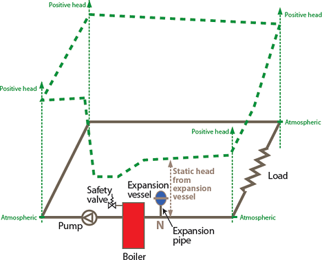
Figure 4: Appropriate location for expansion vessel
Designing for expansion
The proper calculation methods for the sizing of expansion vessels are in BS EN12828 2003 Heating systems in buildings — design for water-based heating systems and for commercial systems reiterated in CIBSE AM14 Non-domestic hot water heating systems. These vessels are selected to satisfy the thermal expansion of the water in the systems. However, there are specific requirements that must be followed to meet the standard.
In addition to the water volume resulting from thermal expansion, the expansion vessel should have a minimal water reserve to compensate for possible water losses in the system. So expansion vessels with a capacity less than 15 litres should accommodate at least 20% of this volume as a water reserve. Expansion vessels with a capacity greater than 15 litres should accommodate a water reserve of at least 0.5% of the total water content of the system, however they should have a capacity of no less than 3 litres.
The vessel will be selected based on the need to maintain a minimum static pressure at any point in the pipework as well as being able to accept the expanding water.
The minimum pressure for the expansion vessel would be determined by the static head at the point that the vessel is connected to the system, plus the vapour pressure of the water at the operating temperature (for example 47.3kPa @80°C) plus a safety margin.
This is to ensure that the pressure at the highest point in the system will be high enough to prevent water vaporisation and air being released from water. The absolute maximum pressure for a system is related to the weakest point (for example, radiators or boiler); however, the normal working maximum is determined from the operating temperature allowing for some overshoot due to control hysteresis and fault conditions.
In the case of a heating system this may be determined by a “limit stat” set at 5K over normal maximum working temperature. (For chilled water systems in the UK the maximum working temperature may only be 30°C: the maximum ambient temperature when the system is out of use). When determining the required capacity of the expansion vessel the minimum and maximum pressures are used to calculate the ‘acceptance factor’ that is then applied to select an appropriate size from manufacturers’ data.
Calculations to determine the appropriate expansion vessel for heating systems must be undertaken in accordance with BS EN12828 2003, with a worked example being available in CIBSE AM14 (2010).
The actual cold fill pressure should be determined in accordance with the standard for the actual vessel selected so that there is always adequate water reserve in the vessel. Commonly used fixed gas vessels (membrane or bag type) are subject to degradation of the rubber (organic) CPD Programme diaphragm. So the vessels lose their ‘pre-set gas pressure’ at varying rates and any calculation method must reflect this operational reality. In cases where a chemical inhibitor (or antifreeze) is added to the water, care should be taken to ensure compatibility with the diaphragm, and other sealed system components.
In the case of chilled water systems the cold fill pressures should also be adjusted to take into account the fact that the system water volume will contract upon start-up and not expand. It is critical to maintain the water reserve as a vessel with no reserve has no ‘hydraulic back pressure’ and the system can effectively act as though no vessel is installed.
The expansion pipe, that connects the vessel to the system, is crucial to correct system operation. It must be able to absorb the rate at which the system expands/ contracts and provide hydraulic stability to the system as valves open/close and pumps stop/start etc, thus avoiding sharp pressure fluctuations. It is sized according to the maximum thermal load that can be delivered into the system. It should be independent of any other function and the connection should always be located on the suction side of the pump and as such becomes the neutral point on the system. Also by placing it before the boiler the temperature is at its lowest so causing least thermal strain on the diaphragm that separates the system water from the inert gas or air that pressurises the vessel.
Different manufacturers are likely to have different tolerances according to the design and construction of their particular vessels, so it may not be possible to simply swap vessels from one company with the same nominal size of another, without comparing the working range. An appropriate confirming calculation should be recorded to ensure that the supplied vessel is appropriately sized.
Expansion vessels in operation
The expansion vessel should be considered critical to system operation. Too often it is thought of as a commodity item and ignored as a vital piece of equipment that requires regular programmed maintenance.
When installed on old systems that have the requirement for regular water make up the incoming refill water will introduce increased levels of dissolved air. Devices such as Vacuum Deaerators (as in Figure 5) may be employed to provide pressurised make up water but with the benefit of removing all dissolved air from the water before it gets into the system. This reduces the potential for continued oxygen-based corrosion.
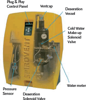
Figure 5: Combined water make up unit and deaerator
By designing systems with appropriate pressurisation the free air in a system can be maintained at a minimum so reducing corrosion (and resulting ‘sludge’), and can reduce the need for chemical treatment whilst improving the life cycle effectiveness of the system.
© Tim Dwyer With thanks to Martin Wilkinson of Spirotech for technical input.