
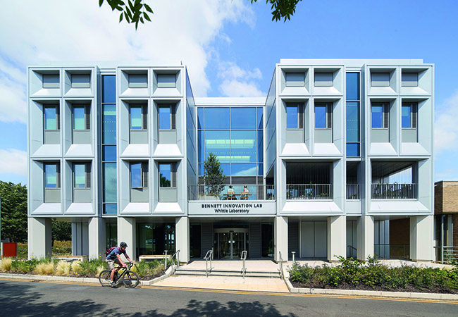
The new Whittle Laboratory is home to the National Centre for Propulsion and Power
Client: University of Cambridge’s Estates Division and Department of Engineering Contractor: SDCProject team
Architects: Grimshaw (design), RHP (delivery)
Engineering consultants:
Max Fordham (MEP, Breeam and acoustics)
Smith and Wallwork Engineers (civil and structural)
Roger Parker Associates (MEP delivery)
Sweco (civil and structural delivery)
Project management: Aecom
Cost management: CB3
Landscape design: Turkington Martin and Liz Lake Associates
Clerk of works: Hickton Quality Control
Commissioning compliance manager: Banyards
The new Whittle Laboratory at the University of Cambridge is designed to accelerate the development of the technologies that could help aviation achieve a zero carbon future.
Home to the National Centre for Propulsion and Power (NCPP), the £58m facility takes its name from Sir Frank Whittle, who developed the first jet engine at Cambridge. The laboratory is an expansion of the 1970s laboratory building, which it adjoins, on the university’s West Cambridge campus.
Conceived along similar lines to facilities for Formula 1 car development, the 4,000m2 building is designed to bring together researchers, industry and technology in an environment geared towards shortening the journey from concept to implementation for fans, compressors and turbines.
Here, researchers can develop a concept, fabricate a prototype in the building’s rapid-manufacturing facilities, test it in conditions designed to simulate real-world aviation or power conditions, and then feed the test data back into the next iteration. The intention is to compress development cycles from years to weeks.
Designed by Grimshaw Architects, working with building services engineers Max Fordham, the laboratory features a triple-height space that houses a unique, £14m cylindrical, variable-pressure, -temperature and -density wind tunnel, which has a rotating rig for testing components under simulated operating conditions.
‘The wind tunnel is the focus of the building,’ says Andrew Johnson, partner at Max Fordham.
Providing the infrastructure to support this facility was one of the defining challenges for the building services engineers. The wind tunnel requires a substantial electrical supply for its 4MVA drive system, while simultaneously rejecting up to 4MW of heat generated by the process plant.
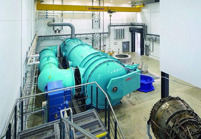
The 4MW wind tunnel is the focus of the building
Powering up the test hall
The task was made all the more challenging by the considerable noise and vibration generated by a rig, designed to test components for high-speed turbines, within a building intended to encourage openness, interaction and the chance encounters between researchers from which new ideas can emerge.
The test rig runs intermittently. To ensure sufficient power is available, the high-voltage supply to the West Cambridge campus had to be upgraded and a new substation installed.
‘We had to negotiate with UKPN [UK Power Networks] to get the site’s high-voltage ring upgraded from 8MVA to 10.3MVA, to accommodate this big increase in the electrical load,’ explains Johnson.
The unit’s high-powered 4MVA drive system is contained within the NCPP Test Hall. To enable 4MW of heat to be removed from it, Max Fordham had to supply cooling water to the tunnel’s 200mm flanged connection at flow/return temperatures of 36°C/55°C.
‘Providing cooling for the unit was challenging, because it’s a really, really peaky instantaneous high load,’ says Johnson.
Max Fordham looked at various cooling options before settling on a bank of four roof-top adiabatic coolers dedicated to the process load. ‘Based on the cooling load, the site’s acoustic constraints and the Energy Cost Matrix [see panel], adiabatic cooling was clearly the best way to go,’ adds Johnson.
The rig will not be able to achieve maximum cooling on days when the ambient dry bulb air temperature is above 30°C.
‘If the air temperature is above 30°C outside, the adiabatics wouldn’t allow you to deliver 4MW of cooling while meeting the site acoustic constraints demanded by the planning requirements for the West Cambridge Masterplan, (46 dB LAeq,1hr at the site boundary)” explains Johnson, who adds that the researchers understood the rationale for the limitation and were confident they could work with this constraint.
The Energy Cost Matrix (ECM) relates the total life-cycle energy required to construct, operate, maintain and take down the building to the construction costs. It was developed by the late Sir David MacKay, former chief scientific adviser to the Department of Energy and Climate Change, to prioritise whole life energy minimisation, operational efficiency and long-term adaptability. The matrix was applied to both the building services and the architecture. Johnson says it had ‘a big impact on the design of the building envelope’. When applied to the building services, he adds, you have to factor in the capital cost of the plant and the embodied carbon of all the different installations, plus the ongoing energy cost of the different options. For domestic hot water (DHW), the ECM steered the team towards point-of-use DHW heaters. ‘We looked at the two options: having a standard calorifier with hot-water circulation; and electric point-of-use units,’ Johnson says. ‘The Energy Cost Matrix proved it was better to have local point-of-use heating, because there’s no circulation pipework or heat losses.’Energy Cost Matrix
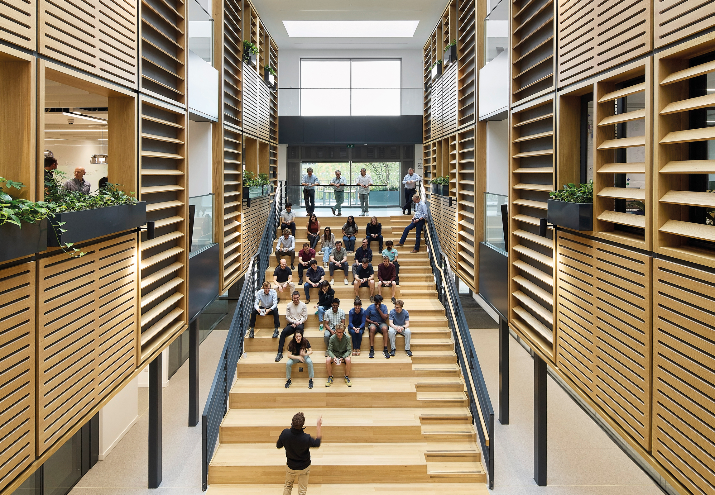
The central atrium is acoustically separated from the workshops and test areas
Cooling for the future
Five 1,340kW adiabatic coolers have been installed. One unit provides space cooling for the wind-tunnel laboratory, with the remaining four units dedicated to keeping the process equipment cool. Space has also been provided on the roof for an additional adiabatic cooler, to future-proof the installation should the testing regime evolve to require more cooling in future.
The wind tunnel is operated remotely and is incredibly noisy. When it runs at full speed, noise levels in the laboratory can exceed 100dB – sufficiently high to require stringent hearing protection and restrict occupancy. Vibration is mitigated by the mass of the laboratory’s 1,700mm-thick concrete foundation supporting the compressor and motor. To minimise airborne noise, the laboratory is separated from the office spaces to the south by workshop spaces, which house the facility’s rapid-manufacturing tools used to fabricate the components that will be tested.
As part of the acoustic design, the ceiling and walls of the laboratory incorporate large areas of acoustic absorption. Max Fordham undertook extensive acoustic modelling of
the whole building to ensure resultant noise levels and reverberation times were within prescribed limits.
The building’s central atrium also has acoustic panelling on the walls and an acoustically treated soffit. After passing through the three-storey building’s colonnaded entrance, visitors arrive in the central atrium. ‘It’s a really collaborative open-plan space, so reverberation control was key,’ says Johnson.
Professor Robert Miller, chair in aerothermal technology and director of the Whittle Laboratory, describes the building itself as ‘part of the machine designed so ideas move from thinking to fabrication to testing’.
The atrium is the heart of this machine, and a key component of its philosophy of collaboration and idea sharing. It is designed to support informal presentations and the exchange of ideas through gatherings of researchers and students. Researchers’ offices are clustered around the atrium, on the first and second floors, with many featuring windows opening directly out onto the space.
On the first floor, opening to the atrium, is a space to house The Whittle ‘Tea Table’ – a giant table, salvaged from the original building, with enough spaces for a large number of the building’s occupants to sit around and chat.
The atrium is also a key element in the building’s ventilation strategy. In addition to flooding the space with daylight, its five saw-tooth rooflights incorporate louvres. These enable stack ventilation, with warmed stale air exiting through the louvres while pulling outside air in through a combination of manually openable windows and automatically controlled louvres across the office floors. This gives researchers the option of natural ventilation when conditions allow.
‘We were heavily involved in the façade design with Grimshaw, to minimise solar loads and maximise daylighting to offices and the atrium, and to use natural ventilation wherever we could,’ says Johnson.
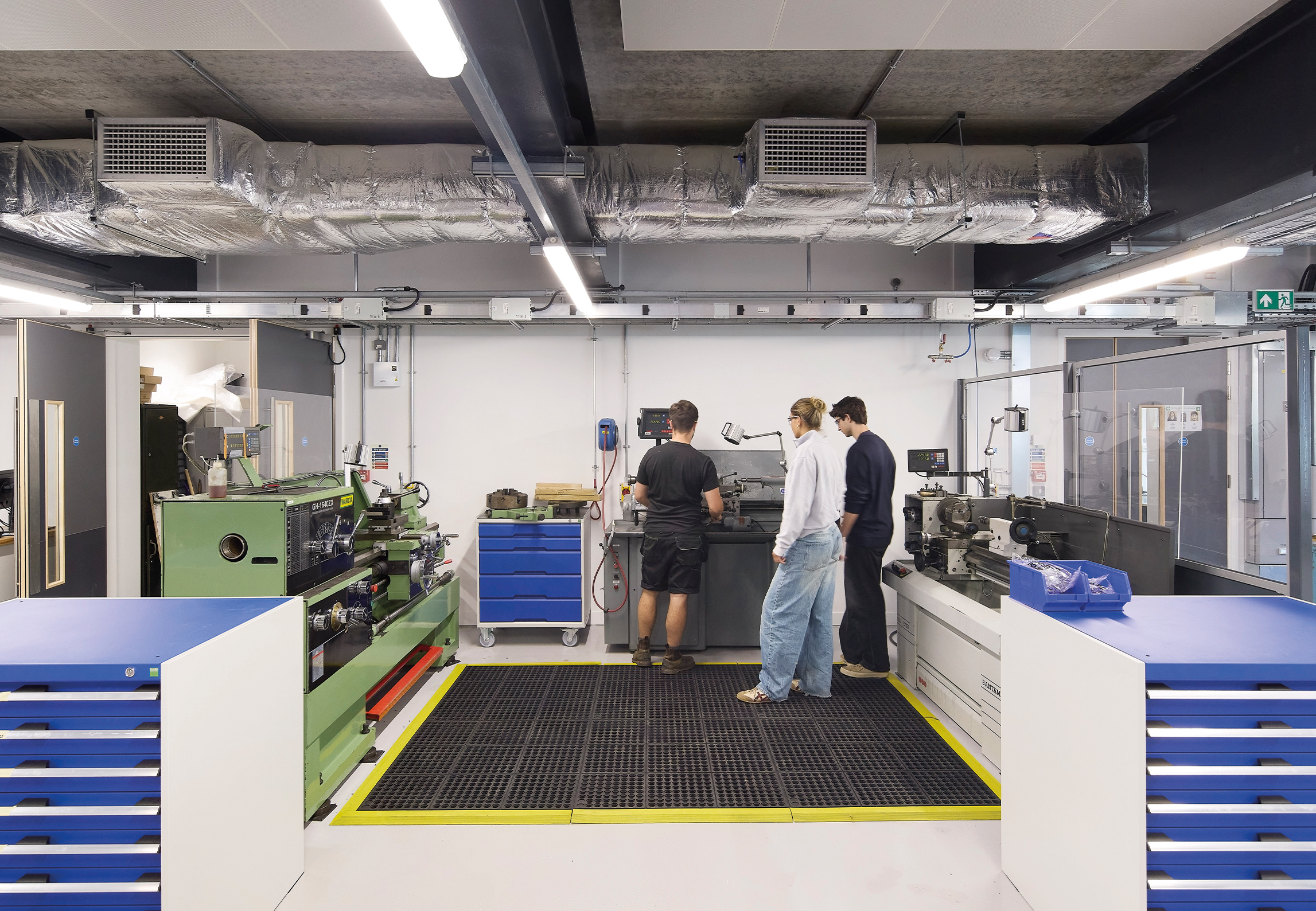
Exposed services will simplify future adaptation
Natural ventilation
Extensive thermal modelling showed that natural ventilation would keep most spaces comfortable for a large part of the year. ‘The idea is that the office windows open to the atrium and the office doors remain open; everything is designed to work with that scenario,’ explains Johnson.
At times when office windows are closed, ceiling-mounted fan coil units (FCUs) provide heating and cooling to the majority of offices. A few spaces are heated using low temperature hot water (LTHW) radiators, while the central atrium and building’s library are kept comfortable using underfloor heating. ‘It’s a mix and match approach to heating, depending on how the spaces are used,’ says Johnson.
He adds that comfort modelling was undertaken for 2050 and 2080 future climate scenarios. ‘The modelling showed that the building would remain comfortable in 2050, but would overheat in 2080 without additional external shading or a decrease in the G-value of the glazing, or both.’
Not all offices are open to the atrium: on the upper floors, there are cellular rooms for those who need a space for uninterrupted thinking, writing and research. Other rooms house the graphics processing units-based computational tools running AI to analyse data harvested from the test rigs, to further compress development timelines. These spaces are fully air conditioned.
Max Fordham’s brief was for a fully electric building, so two 100kW roof-mounted reversible air source heat pumps provide heating and cooling. In addition, a 125kW chiller on the roof has been installed to provide top-up cooling for peak summer loads.
Three roof-mounted air handling units, incorporating heat recovery, LTHW coils and chilled water coils, provide tempered fresh air to the rooms.
There is also provision for future connection to the heating and cooling mains of Cambridge West District Energy Network. The university asked the team to look into using the 4MW of heat recovered from the wind-tunnel drive motors elsewhere on the campus, via the district heat network. ‘The practicalities of storing 4MW of intermittently generated heat just wasn’t feasible,’ Johnson says.
In a facility designed to encourage rapid innovation, the building services have to be able to respond. As a result, they have been designed to be easily adapted and upgradable to support developments and innovations over the coming decades. ‘A lot of the services are exposed, or accessible through the raised access floor – so if the NCPP wants to reconfigure the spaces in future, it’s all fairly easy.’
Mechanical plant occupies most of the roof space, with the exception of two areas. There are blast panels in the roof above the wind-tunnel hall, which are designed to blow out in the event of a catastrophic failure of a test. There is also a large area of photovoltaic panels, which generate 34.6kWp.
To ensure the carbon impact of a building designed to support research into net zero aviation was minimised, the design team used the Energy Cost Matrix to make carbon-efficient selection of plant and materials. Embodied carbon was further reduced by reusing the raised floor tiles reclaimed from the laboratory that previously occupied the site. ‘The design team monitored the embodied carbon up to construction commencement,’ says Johnson.
However, the embodied carbon figure for the building is hugely skewed by the large amounts of concrete used for the structural foundations of the NCPP process plant, so does not provide a meaningful comparison against LETI targets.
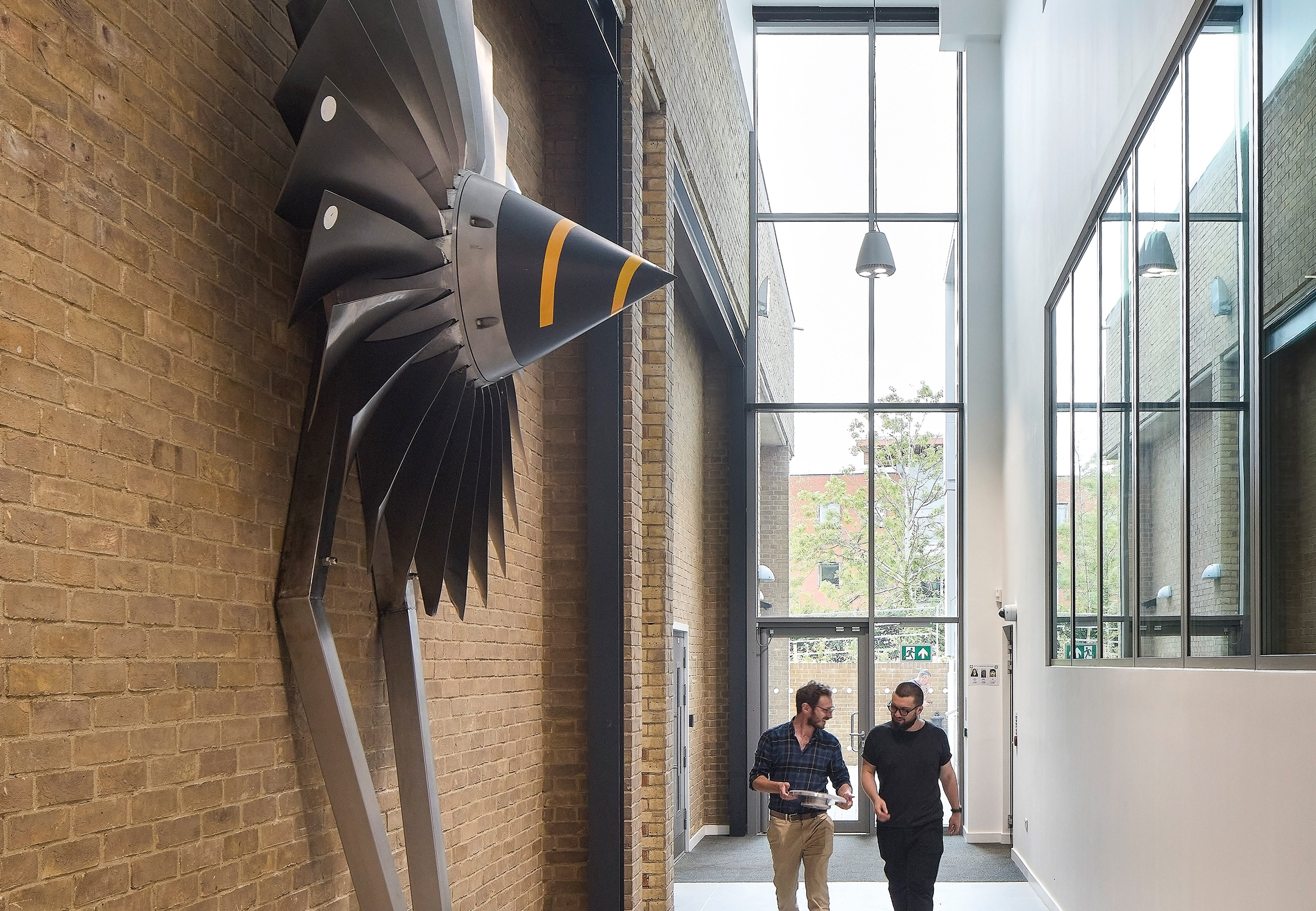
Exposed services will simplify future adaptation
Preparing for take-off
The laboratory opened on 20 July 2026, and Max Fordham is currently undertaking a post-occupancy evaluation of the building services. It has picked up on a few niggles, such as the controls on some FCUs being set incorrectly.
The study has also highlighted that a few of the areas are not being used as originally envisioned. ‘We’re working with the university to sort out a few minor tweaks,’ says Johnson.
It is expected to take up to two years before the wind-tunnel is fully operational so that research at the NCPP can really take-off