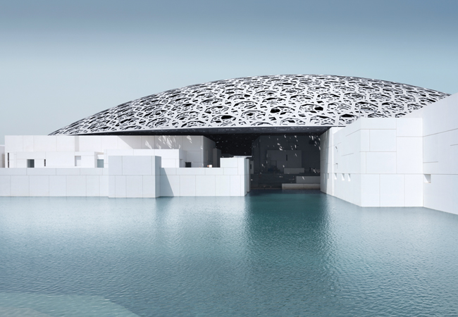
Louvre Abu Dhabi exterior © Louvre Abu Dhabi, Photography: Mohamed Somji
Designed by French architect Ateliers Jean Nouvel, Louvre Abu Dhabi comprises 55 buildings laid out in an organised jumble beneath a giant, silvery, lattice dome. This 180m-diameter cupola is made up of eight layers of steel and aluminium, which form 7,850 star-shaped perforations of various sizes. Through these gaps, sunlight dapples the azure waters of the Arabian Gulf surrounding the complex, and mottles the white walls of the museum’s 23 permanent galleries.
The Emirati art gallery opened in November and is home to some of the world’s most valuable artworks. It is supported by Agence France-Muséums (AFM), the organisation of which the Paris Louvre is a part. AFM indicated precise environmental criteria for the gallery spaces to the Department of Culture and Tourism – Abu Dhabi (DCT) and Louvre Abu Dhabi.
‘Gallery conditions were recommended at 21°C, plus or minus 1°C, and 50% relative humidity (RH), plus or minus 5%,’ says Mark Owen, associate director at BuroHappold Engineering, the project’s MEP engineers. This is no easy task in an Emirate where summer temperatures can reach 45°C and RH levels in winter can exceed 60%.
In addition to the galleries, the strict environmental criteria had to be maintained in four vestibule areas, a highly secure conservation building, and some back-of-house spaces; the requirement even applied to some of the lifts and lift shafts.
For the non-gallery areas of the 58,000m2 scheme – including the cluster of entrance buildings, the ubiquitous shop, a gourmet restaurant, cafeteria, children’s gallery and an auditorium – AFM set a slightly more relaxed design criteria of 21°C +/- 5°C and 50% RH +/- 5%. ‘There are two levels of environmental control: close control and not quite so close control,’ laughs Owen.
AFM also set criteria for airflow in the galleries, which it wanted to flow over the artworks in a laminar fashion, to avoid hot or cold spots. ‘We couldn’t use displacement ventilation, for example, because that would have created temperature stratification, and AFM would not permit a temperature differential to occur across any of the artworks,’ explains Owen.
Ventilation
The engineers were helped in developing the ventilation solution by the galleries’ low fabric-infiltration rate. ‘To protect the art from pollution, sand, temperature and humidity fluctuations – and to save energy – the client specified an infiltration rate of just 2m3/m2.h at 50Pa,’ says Owen. With the exception of the aluminum and steel dome, the complex and its two basement levels are constructed from cast in-situ concrete, up to one metre thick in places. Envelope construction is the same for all the galleries, although the size, shape and volume of each one is different.
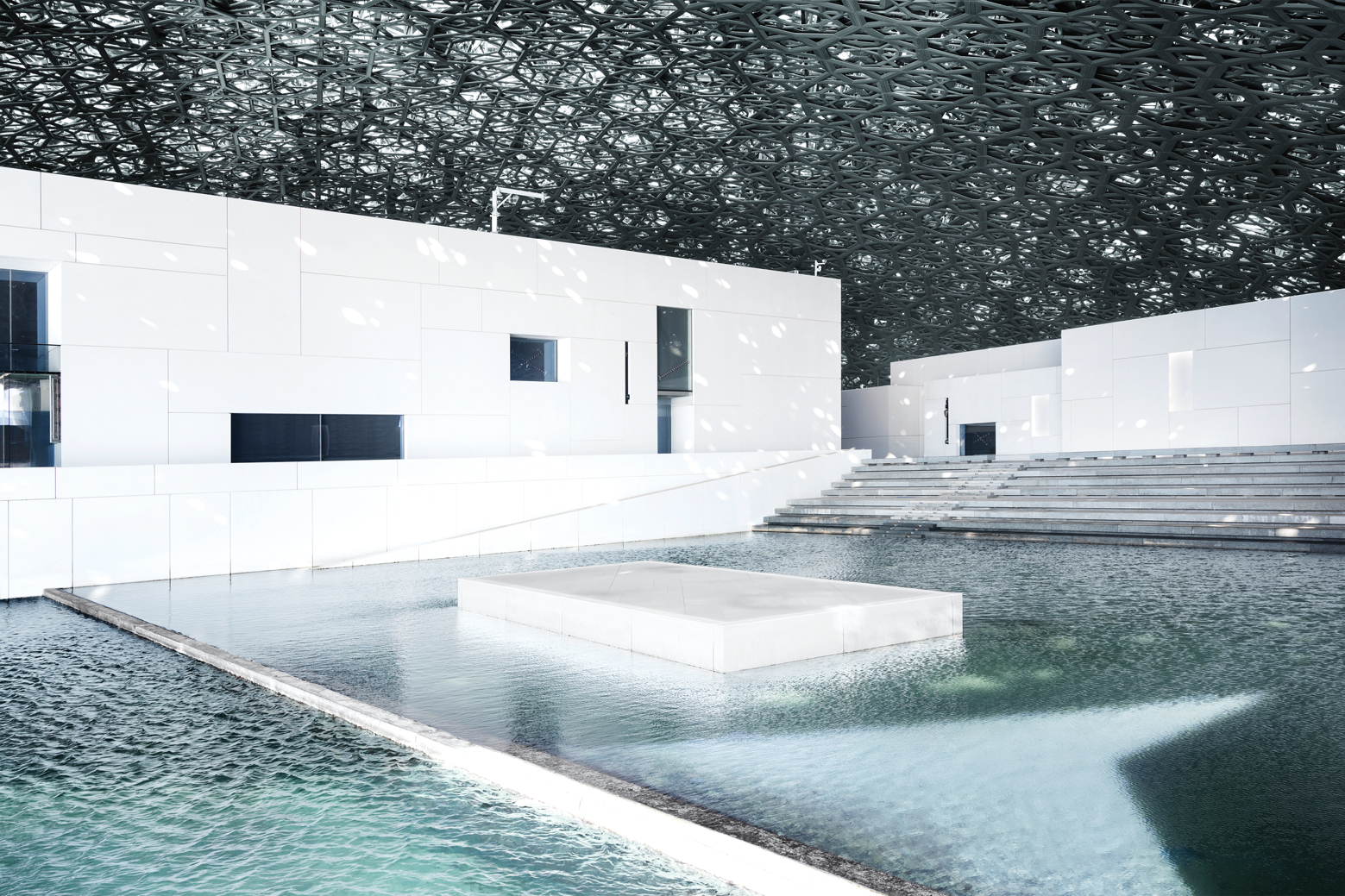
Louvre Abu Dhabi's plaza © Louvre Abu Dhabi, Photography: Mohamed Somji
Laminar air flow in the galleries is achieved using ceiling-mounted Kiefer linear diffusers. Extract is, predominantly, through low-level grilles mounted in the walls; there is also a nominal amount of extract at ceiling level. ‘The galleries are a minimum of five metres high; the art zone extends up to four metres from the ground, which means the air diffusers basically have one metre in which to achieve a laminar flow before the art zone, without hot or cold spots,’ says Owen.
Although computational fluid dynamics (CFD) modelling had shown the design solution to be effective, it was decided to construct a full-size gallery mock-up at BRE’s Watford campus, to test the performance of the diffuser and that of the CFD model. ‘The mock-up verified the modelling, which allowed us to roll out the design across all of the galleries, confident that the scheme would perform as designed,’ Owen says.
Each gallery has dedicated run and standby air handling units (AHUs) concealed in the 10m deep, double-height basement, an arrangement that improves security and allows the plant to be maintained without engineers having to access the galleries. The standby unit is in place because the client did not want the failure of a single item of plant to jeopardise the environment protecting the artworks. In total, the museum has 108 AHUs and 43 close-control units serving the smaller rooms and galleries.
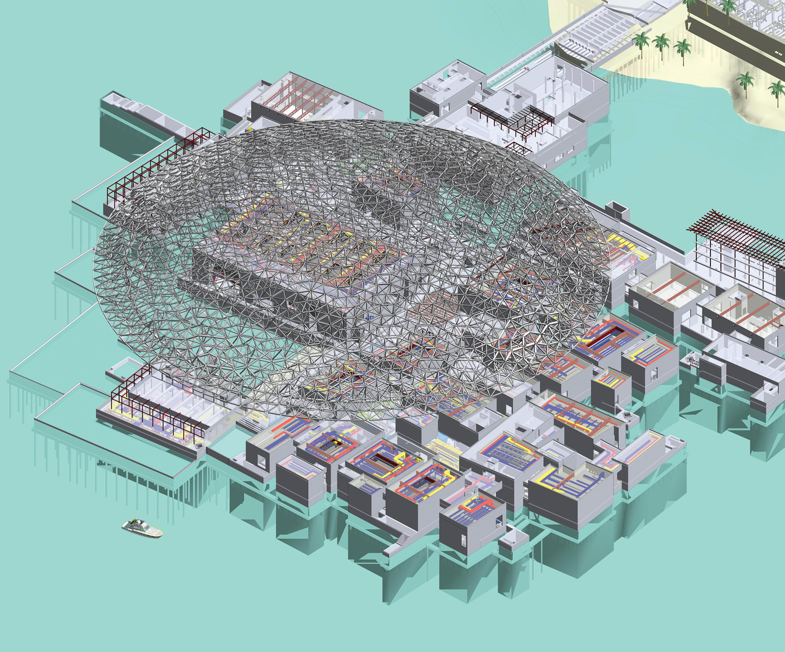
A total of 55 buildings are housed beneath the gallery’s lattice dome. Credit: BuroHappold Engineering
Having dedicated AHUs serving each gallery ensures environmental conditions can be maintained independently of the other galleries. Each gallery’s AHU draws fresh air from what Owen calls ‘the fresh air ring’ and discharges extracted air to the ‘exhaust air ring’. These ‘rings’ are, effectively, giant loops of ductwork distributed around the basement in a services tunnel, to serve the building and all gallery AHUs and close-control units.
The fresh air duct ring is supplied with conditioned outside air by four large primary AHUs (three duty, one standby) mounted in the central basement fresh air plantroom. They have stainless steel sand-trap louvres on the intakes, to prevent the desert sand from entering the units and to help resist corrosion in the marine environment. The secondary AHUs of the gallery systems connect to these primary ring mains. ‘This arrangement allows much smaller AHUs to be used to supply the galleries – it’s like a giant fan-coil system, to put it crudely,’ explains Owen.
The volume of air supplied by the primary units varies, based on the fresh air loads required to keep CO2 levels below 600ppm and on the need to maintain the galleries at a positive pressure, to prevent the ingress of unconditioned outside air. Extracted air is returned to the primary AHUs, where useful energy is reclaimed using enthalpy wheels.
‘The primary air handling units deal with all the fresh air load, while the gallery units do the air conditioning,’ says Owen. ‘We used this system because it gives us a level of operational safety: if ever there was an issue with the primary air plant, it could be shut down while the gallery systems continue to operate in isolation.’
The entire air system was tested over a 28-day period before handover, as part of the validation process for acceptance by AFM.
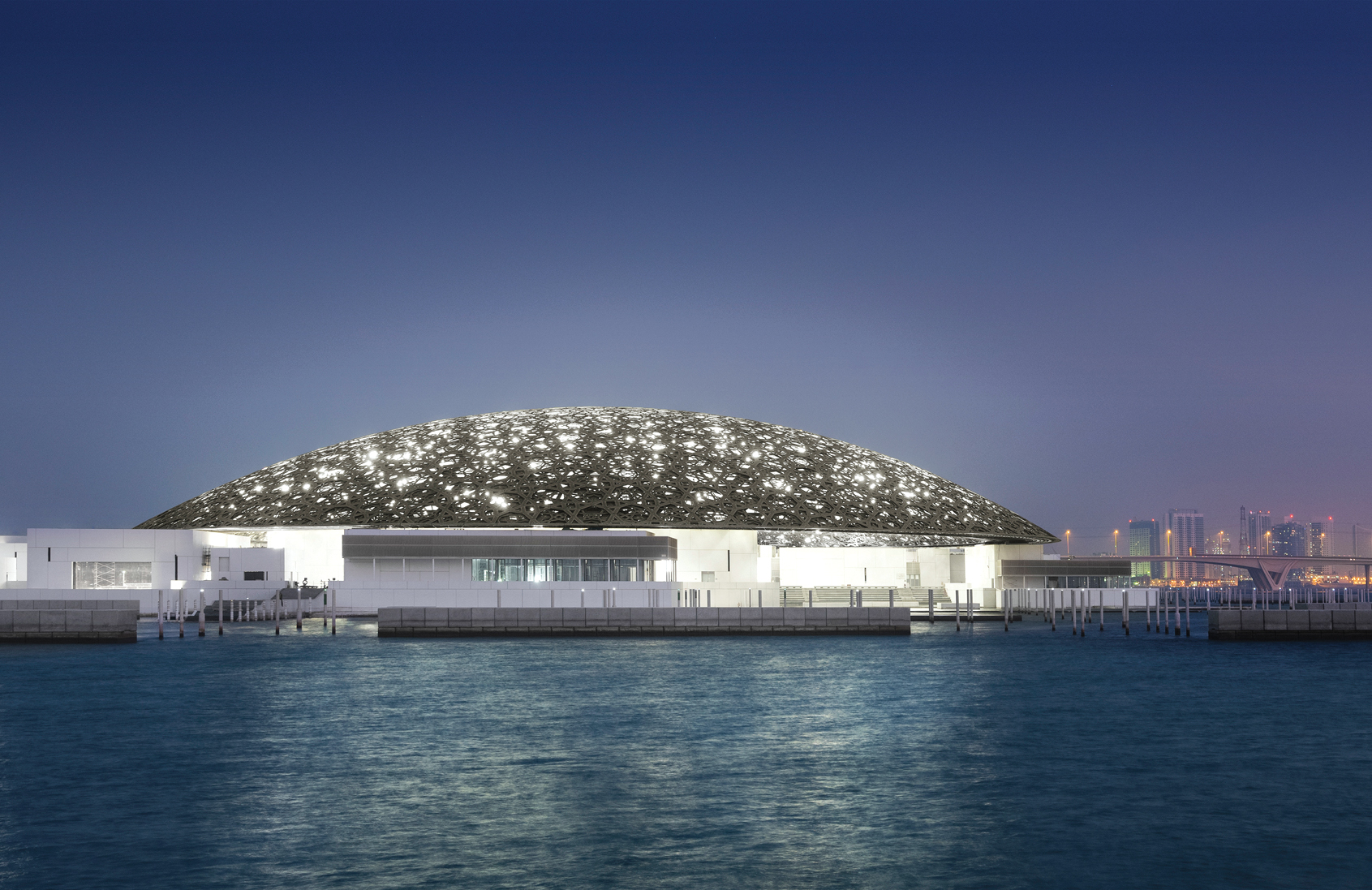
Louvre Abu Dhabi's exterior © Louvre Abu Dhabi, Photography: Mohamed Somji
Fire protection
Operation of the supply air system is relatively straightforward under normal conditions. Under fire conditions, however, things get more complicated. ‘The cause and effect analysis we undertook was the most complicated I have ever worked on,’ says Owen.
One of the challenges was that the museum could not have inert gas or water fire-suppression systems in the galleries and spaces where artworks are housed. Local building codes, however, required sprinklers to be installed. As a result, BuroHappold’s fire engineers had to develop a bespoke smoke-ventilation solution that would be acceptable under the Emirate’s fire rules, but would eliminate the need for sprinklers. According to Owen, the starting point in developing the solution was to make every gallery a fire compartment. ‘Should a fire break out anywhere in the museum, all the gallery ventilation systems will switch to full recirculation to protect the artworks,’ he says. At the same time, the main fresh air plant would be switched off and isolated.
If the fire was in one of the galleries, the gallery would be isolated from the remaining spaces by fire shutters, and the ventilation system for that room would switch to smoke-extract mode. In normal operation, air in the gallery moves in a downward direction, from the ceiling supply to the low-level extracts. In smoke extract mode, however, the air moves in an upward direction, as smoke-extract grilles in the ceiling pull smoke from the gallery via a dedicated smoke-ventilation system.
“CFD modelling had shown the design solution to be effective, but it was decided to construct a full-size gallery mock-up at BRE”
Make-up air is supplied to the gallery by separate supply fans located in the basement, which provide an increased air volume via the fresh air rings. The make-up air bypasses the gallery AHUs and is routed to low-level and in the gallery and supplied through what were the low-level air extracts. ‘There are some very clever damper arrangements in the gallery plant rooms,’ says Owen.
Predictably, the architect did not want his creation marred by visible building services plant or flues. Because of the museum’s in-the-round, island location, the main energy centre is remote from it, buried out of sight on the adjacent Saadiyat Island. The plant is linked to the museum via a service tunnel under the sea – the same tunnel used to deliver art to the museum in air conditioned vehicles.
Daylight and the artworks
The majority of the galleries are sheltered from the searing Arabian sun by Louvre Abu Dhabi’s lattice dome. Most incorporate a rooflight and some even have windows overlooking the sea. One of the key challenges for BuroHappold was to ensure sunlight would never fall on the artworks.
The engineers modelled the path of the sun over 365 days. Then, using BIM technology, they developed the dome’s complex, multilayered design to allow the sun’s rays to permeate the galleries without touching the art.
To achieve precise levels of light in rooms that have a combination of natural and artificial light, BuroHappold’s New York office produced a series of reports that predicted the sun’s path and anticipated daylight levels for each gallery. The reports even took into account the sensitivity of specific artworks to light.
All windows and rooflights incorporate three blinds – two to diffuse daylight and a third to act as a blackout blind. These operate automatically, based on a schedule produced by the modelling, combined with the output of light sensors giving real-time data. If light levels get too high, the blackout blinds prevent the possibility of damage to the artworks.
Desert heat
There are no chillers in the energy centre because it is fed by 10.5MW of chilled water from the island’s district cooling plant. There are, though, heat pumps and – surprisingly in the desert – boilers too. ‘The heat pumps and boilers are there to reheat the fresh air supply, because it has to be cooled to such an extent to dehumidify it, that it has to be reheated to maintain the supply condition,’ says Owen.
In fact, the boilers are only installed to provide backup to the heat pumps. These have been designed to take heat energy from the chilled water return, which is used to reheat the fresh air. Once the useful heat has been extracted, the cooled water from heat pumps rejoins the chilled water return – an arrangement that helps reduce the cooling load on the district cooling system.
The plantroom is also home to 10 transformers – six large 22kV transformers at 1,500KVA, and four smaller 11kV transformers, also at 1,500KVA. There are five emergency generators. Four 2.25MVA units, developing 11,000V, are located in the energy centre, and supply the four 11kV transformers. The 630kVA generator is on top of the conservation building as a precaution, should everything in the energy centre fail – what Owen calls ‘the doomsday scenario’. At such times, the museum can move the art into the conservation building, which has its own dedicated, stand-alone chillers and air handling systems. It is entirely self-supporting, to protect the valuable artworks using building services – which, themselves, are a work of art.
Project team
Client: The Tourist Development and Investment Company of Abu
Dhabi (TDIC)
Architect: Ateliers Jean Nouvel (AJN)
Executive architect: Pascall+Watson
MEP Engineer: BuroHappold Engineering
Contractor: Joint venture between Arabtec Construction, San Jose SA and Oger Abu Dhabi