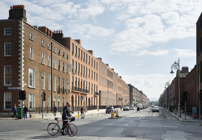
The Electricity Supply Board’s headquarters front onto Fitzwilliam Street in Dublin
The Electricity Supply Board (ESB) is majority owned by the Irish government, providing generation and distribution of electricity in Ireland and internationally. It has a target of being carbon neutral by 2040, and is investing heavily in renewable generation and associated technology, such as energy storage.
The redevelopment of its Dublin headquarters was an opportunity to contribute to the advancement of sustainable office development. To reflect this, a passive design approach has been taken, working with the local climate to minimise heating and cooling loads. Unsurprisingly, the ESB has moved away from gas to embrace heat pumps with heat recovery, while ventilation is a combination of natural and hybrid solutions.
The project contains two office buildings within one city block. The first is ESB’s headquarters, which will also serve as a research tool; it is hoped that it will provide a source of intelligence on new techniques and technologies that will influence the next generation of offices. The second building includes many of the same techniques, but is optimised for the commercial market.
To date, zero active cooling energy has been required in the open-plan office building
Almost all large commercial offices are sealed, air conditioned buildings with traditional services, so it was important to create a sustainable alternative that could stand as a precedent. Dublin’s commercial market approved of the approach, placing a value on the building that covers the full cost of the development of both offices.
The design follows first principles and focuses on minimising energy demand. The use of fully glazed facades was explicitly banned in the design competition brief because they can lead to excessive heat losses and heat gains which increase energy usage.
In an unusual step, BDP M&E were appointed to assist with judging the sustainability aspects of the architectural competition, and developing the architectural brief so that sustainability was a key project outcome.
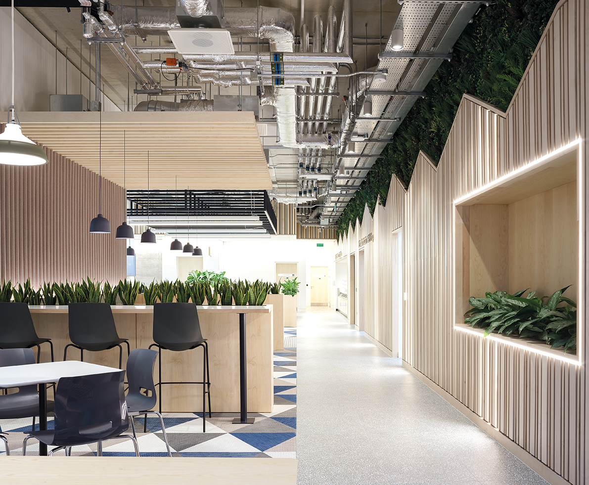
In cellular spaces, an innovative technique was used that links the inlets to the fan coils directly to the open-plan space, so that large volumes of air exchange occur
Glazing areas were adjusted by location, with smaller areas on the more exposed upper floors. South- and west-facing glazing is provided with solar control, while solar gains are encouraged from the north and east. South-facing façades have vertical external shading, optimal for blocking solar gains in the afternoon.
A strip of 1.5m of exposed mass is used at the perimeter, raising the glazing level and projecting daylight deeper into the plan. Deeper plan areas are mainly reserved for tea stations and have open, timber grid ceilings. This allows the concrete soffit to be thermally visible while offering the visual benefits of a ceiling.
A 70% ground granulated blast-furnace slag (GGBS) content was used in the foundations, and 50% for the structure, resulting in a reduction of 160 kg CO2 equivalent per m2.
Hybrid ventilation
Modern offices have a net cooling requirement throughout the year. External temperatures in Ireland are almost always lower than required internal temperatures, so sealing offices and actively cooling them may not make the best use of free cooling. The insulation and low infiltration levels of sealed buildings is likely to have a negative effect on cooling.
The hybrid ventilation solution used at ESB combines the best of natural and mechanical ventilation, and active cooling. In combination, better air quality is produced, with lower energy usage, than by each individual solution.
The concept of opening windows in an air conditioned building is commonly frowned upon because of concerns that cooled air will be lost. However, such losses can be avoided through the careful control of room setpoints.
The human response to temperature is complex and adaption occurs naturally in warmer weather. After several days of warm weather, tolerance to higher temperatures increases, so maintaining lower internal temperatures can create an environment that is perceived as uncomfortably cold.
An office upper temperature setpoint has been determined using a new control routine, relating the internal temperature to the weighted running mean of the external temperature. Inspiration was drawn from the thermal adaptation discussion within CIBSE TM52. As the resulting internal temperature is almost never below the external temperature, staff are free to open and shut windows (see panel, ‘Window arrangement’).
Timber grid ceilings are used in tea rooms and deeper plan areas, allowing concrete to be thermally visible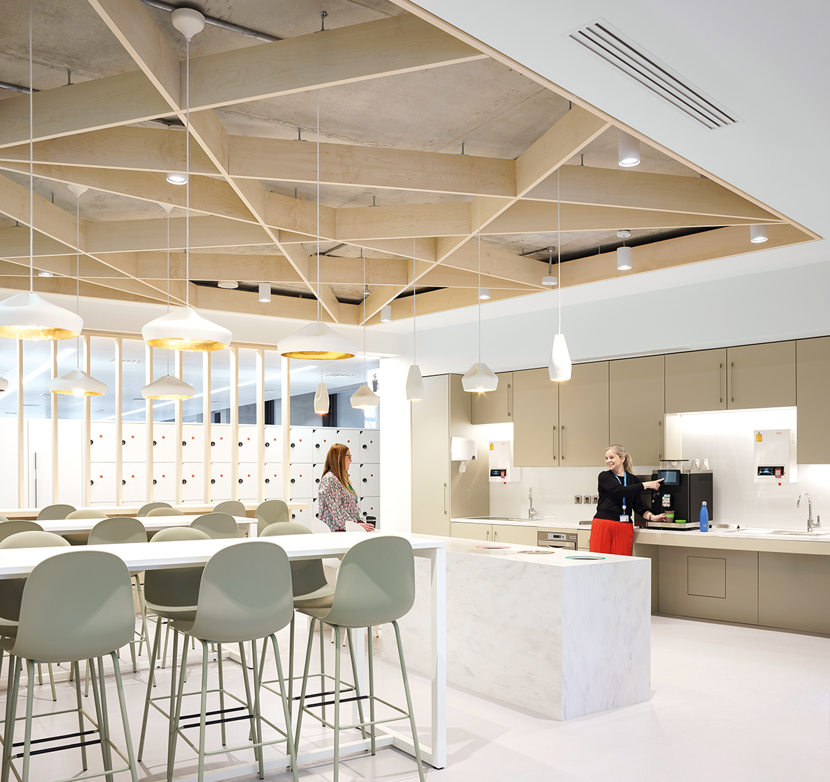
Early monitoring results have demonstrated the effectiveness of the strategy. To date, there has been almost zero active cooling energy required in the open-plan offices, even in external temperatures above 20°C.
Mechanical ventilation
Office air has traditionally been supplied with a constant air volume system, which operates at full volume irrespective of the number of people in the building, often using excessive volumes to take account of meeting rooms and canteens. This simplified approach is taken because of the number of variable air volume (VAV) dampers that would otherwise be required to provide control of internal meeting rooms and other cellular spaces.
The approach at ESB was to use breakout spaces that allow open air exchange with the open-plan areas. In cellular spaces, an innovative technique was used that links the inlets to directly to the open-plan spaces, so that large volumes of air exchange occur, avoiding the need for individual fresh air supplies. This means VAV was only necessary at the main risers on each floor, reducing costs dramatically, and natural ventilation is drawn into internal spaces.
The same technique is used within patch rooms (held at 25°C), which not only provides free cooling, but also recovers heat naturally to the office spaces. The VAV system employs a variable pressure control strategy that reduces fan energy use significantly compared with constant pressure VAV solutions (see panel ‘The variable pressure control strategy’).
The variable pressure control strategy
Most offices use a constant air volume solution for fresh air supply. This means that enough fresh air is provided for everyone in the office even if there are only a few people present. This is very wasteful but is normal practice.
The reason that a constant volume system is usually used is due to the cost of providing VAV dampers to each meeting room. In this case the solution of providing a variable volume of fresh air to the meeting rooms without using dampers unlocks the opportunity to use a variable fresh air supply for the entire building.
Very occasionally a demand controlled variable air volume solution is used to ensure that the volume of fresh air supplied matches the actual demand in offices. (We are not aware of any examples in large offices where full fresh air VAV is used, and CAV is invariably used, but it has been used occasionally in smaller offices).
In that case a constant pressure VAV system is almost always used. The pressure at the air handling unit is set to a fixed value and as VAV dampers close the air volume reduces but energy is still lost across the VAV dampers unnecessarily.
With constant pressure VAV, the fan energy saved is (almost1) directly proportional to the volume so halving the volume only halves the fan energy.
In a variable pressure VAV system, the pressure at the air handling unit is also adjusted. It is adjusted to ensure that at least one VAV damper is always fully open so almost zero energy is lost forcing air over a partially closed damper.
In this solution, the energy saved is proportional roughly to the cube of the flow rate (fan energy is proportional to the square of pressure and is directly proportional to flow). So, the reduction in fan energy is dramatic. We measured an 85% reduction in fan energy for a sample condition by using the method.
There are caveats in that method is most successful when no zone served has full demand but in the hybrid ventilation solution that is almost always the case. Care is required to avoid forcing a worst case to accidentally persist in the system by oversizing the few known constant loads.
During monitoring, we typically see pressures at the AHU in the order of 80Pa – the traditional solution for a building this size would be over 300Pa.
Variable pressure VAV is not widely understood in the industry and writing the control routines to achieve it can be tricky. There are a number of technical papers that discuss the challenges.
It is possible to purchase an off the shelf controller known as a VAV optimiser that will handle the controls but in this case they were programmed into the BMS (after some coaching from BDP).
FOOTNOTE:
1 Providing a constant pressure at the AHU outlet does still reduce the fan pressure somewhat at lower flow rates because the pressure drop across AHU components is lower at lower flow rates. The constant pressure at the outlet strategy does allow some variable pressure to occur within the AHU.
In many traditional systems office ventilation air is supplied at a constant temperature, leading to unnecessary heating and cooling and the loss of free cooling. Several innovative control strategies to supply air temperature are being tested in the offices. A self-learning strategy has been implemented that adjusts the level of free cooling provided in proportion to the net building loads.
A total thermal recovery wheel is also used to provide recovery of moisture during winter. Two air handling units are run in parallel to minimise fan power iat times of low ventilation need. Initial monitoring shows: 85% less fan energy than would be consumed in a typical office building; almost no active cooling required, even with external temperatures above 20°C; excellent air quality.
Heating and cooling
The offices are a zero local pollution building, with no fossil fuel connections, even for cooking. The operational carbon impact of the building will approach zero as the national grid decarbonises.
Initial monitoring shows that almost zero heating was required (monitored data indicates a figure less than 7 kWh.m-2) and that heat was almost entirely recovered from cooling loads such as computer rooms.
Window arrangement
The building is set around a series of planted courtyards, with all office areas having access to external spaces, natural light and ventilation. Setting courtyards back from the street allows for natural ventilation, with less traffic noise and improved air quality.
Lower-level manual openings are provided for staff, with motorised openings at higher level, reducing draughts and maximising airflow. The automated windows adjust appropriately to weather, cracking open when cold, opening fully when warm, and providing night cooling, They can, however, be manually overridden by staff.
Cracking the windows open whenever there is a net cooling load allows for an airtight building in cold weather without compromising free cooling in warmer weather.
An often ignored constraint of opening windows is that, in warm weather, blinds are pulled over the openings to prevent glare, blocking the free flow of air. To prevent this, solid window sections were used, and openings are protected by external shading in the form of vertical fins that do not restrict airflow.
While multipurpose air source heat pumps (ASHPs) allow heat recovery, there are limitations and the coordination of loads by integrated controls results in unexpected losses. So, a dedicated water-to-water shunt heat pump has been included. Heat recovery is guaranteed, without the risk of the air source system cutting in unintentionally.
Similarly, the hot water heat pump is connected directly to the chilled water circuit, ensuring 100% of the load is derived from recovered heat. The conventional arrangement of coupling to the hot side can cause the ASHP to kick in unnecessarily. (See panel “
Cooling is provided using a priority cascade as follows: recovery of cooling from domestic hot water heat pumps; free cooling provided by a 4.8km closed-loop ground collector; cooling recovered from any live heating demands in the building; a phase change store to transfer any remaining heat rejected from heat pumps that are providing cooling.
The phase change material (PCM) which is under test in this building, changes state at 10°C. . In winter, the PCM stores cooling associated with morning pre-heat for use later in the day.
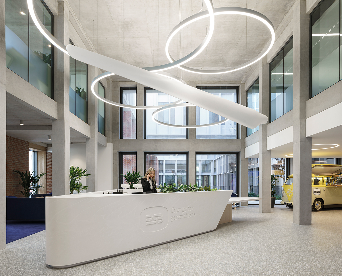
The ESB HQ is also one big research tool for sustainable offices
The fan coils use a single coil with a six-port changeover valve, reducing capital costs, fan energy and embodied energy. A glycol-free system lowers chemical use while improving the heat-transfer properties of the water used.
Monitoring and reporting
The ESB offices are fitted with an extensive metering package, and BDP is undertaking tuning and monitoring of the building as part of a research project. Full details of the methods used in the building, along with data and the resulting insights, will be published.
If monitoring shows big savings in energy and costs, others may be encouraged to go fully electric by switching from gas to sustainable alternatives. ESB’s Dublin office stands as proof that heating and ventilation needs can be met while heading towards carbon net zero.
The use of a multi-purpose heat pump (an air source heat pump that provides, heating, cooling, and heat transfer) is a growing trend for office buildings. Where it is used, a boost heat pump is often attached to the hot side of the heat pump (to the heating system) as per manufacturers recommendations and the boost heat pump raises the temperature of the water to 60oC to heat domestic hot water. In ‘theory’ this allows domestic hot water to be produced by transferring heat from the chilled water system, via the two heat pumps in cascade. In practice what often happens during low loads (most of the time) is that the chiller is not actively delivering cooling when the domestic hot water load kicks in. The chilled water system may still be delivering cooling to the building, but the compressor isn’t actively providing cooling as it is waiting for the chilled water temperature to rise again before kicking in. This means that the heat pump goes into air source mode and domestic hot water is delivered from the air unnecessarily. This phenomenon is not widely understood. In this case. A water-to-water heat pump is used that connects directly to the chilled water side of the system, so it isn’t possible for the heat for domestic hot water to come from the air. If there isn’t a large enough active cooling load at the time the chilled water temperature drops using the water content as a thermal battery. Because the normal chilled water temperature is 13oC in this case (instead of the normal 6oC) there is plenty of capacity. Although in reality there is always a cooling load from the comms rooms that is large enough to heat the hot water. This strategy also requires that the comms rooms (and patch rooms) are cooled with chilled water, which is not conventional but causes no problems. It is difficult to persuade engineers to deviate from the tradition of using DX for comms rooms because there is a concern that water and electrics don’t mix. In reality if the water components are kept outside the comms rooms the risk is negligible. In this building the heat pump is also directly connected to the hot water storage cylinder on the hot side. The domestic hot water goes directly through the heat pump instead of through an intermediary heat exchanger. The traditional use of an intermediary heat exchanger reduces the heat pump efficiency. We even had to get a steel coupling cut off the heat pump (and replaced with brass) to allow us to do this as the supplier assumes the heat pump is connecting to a closed system. Suppliers don’t like direct coupling due to a risk of scaling that can occur if the building is in a hard water area so some caution is required.Using water-to-water heat pump to provide domestic hot water
About the author
Chris Croly is the building services engineering director at BDP