![]()
The UK has at least 14,000 heat networks – of which about 2,000 are district heating and the rest communal – that together supply around 2% of UK buildings’ heat demand.1 The rise of the ‘microgrid’ and the ‘smart’ grid offers increasing opportunities to maximise the utility of disparate, independent, distributed power generation. A recent Ernst and Young report2 ‘estimated that it will cost the same to self-generate and store power as it will to buy from an energy provider by 2022 in Europe’. The general uncertainty in UK grid-supplied electricity has been somewhat abated by the continued ‘capacity market auction’ – which recently purchased backup capacity for the grid at much reduced prices3 – as well as the overall reduction in UK electricity use (demand fell by an estimated 2% in 2017, and since 2010 has fallen by 9%4). However, as the ‘spark-gap’ – the price difference between natural gas and grid electricity – typically reduces, the trend to switch to electricity increases. Nonetheless, high-efficiency gas appliances such as CHP can play a role in the bridge to decarbonisation, and allow local security in the supply.
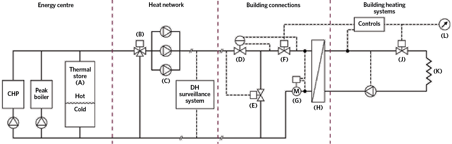
Figure 1: Some typical features of an example efficient heat network5
As with most successful engineering projects, a successful heat network-integrated CHP project is delivered through holistic, joined-up and monitored design implementation and operation. The UK’s heat networks code of practice, CP15, notes that ‘this is often made more difficult by the fragmented nature of the industry and the procurement of schemes. It is common to find that the feasibility work is carried out by a consultant, the detailed design and construction by a design and build contractor, and the operation and maintenance by a separate operating company’. As can be seen in Figure 1 (extracted from CP1), a heat network will cross the domains of several traditional trades and contractors, so will require properly planned integration from the conceptual evaluation of the project through to its operation and management.
The characteristic features illustrated in Figure 1 allow effective integration of CHP into the heat network for it to operate for the longest period of time at the highest overall efficiency. The thermal store, A, is used to minimise the use of the peak (top-up) boiler and maximise income from CHP electricity, as it can be used to absorb heat when there is an economic opportunity to generate electricity but insufficient instantaneous heat demand from the heat network. The control valve, B, can be used to provide variable primary flow temperature. The variable speed pumps, C, are selected so that they can readily meet the range of duties for the demand pattern that would be required to meet the variations controlled by monitoring representative pressures in the heat network.
The differential pressure control valve, D, limits the maximum flow and limits the pressure across the two-port control valve, F, that is used to provide the variable flow to the plate heat exchanger, H. The two-port control valve ensures a variable volume water flow in the heat network that is able to meet the heat demand of the secondary networks in the individual buildings. The temperature-controlled bypass valve, E, maintains flow temperatures above a minimum level at times of low demand.
The plate heat exchanger, H, is selected for a close approach temperature (see Figure 2) to provide the best potential for the heat in the secondary network – CP1 recommends that the approach should not exceed 5K. These are typically the key functional elements of heat interface units (HIUs), and there can be an advantage in employing separate heat exchangers for the heating and the domestic hot-water loads.
The heat meter, G, is used both to encourage careful use of energy (through digital displays) and to provide energy-use data to the user and operator. The two-port control valve, J, maintains low return temperature and would include a balancing facility to set flowrates and the return temperature. Individual heat emitters, K, are sized to give low return temperatures, increasing the use of the potential heat from the system. The local control, L, should provide an easily accessible interface to the non-expert user as a means of setting and monitoring desired heating and hot-water requirements.
In the UK, the companies licensed to distribute electricity – the distribution network operators (DNOs) – are concerned about embedded generation that can potentially imbalance the electrical supply grid. However, the use of synchronous CHP units – which can be operated in isolation from the grid or used in parallel with it – helps to ensure a robust supply. Smart grid technology can allow DNOs, in particular applications, to access technology remotely to match load supply and demand.
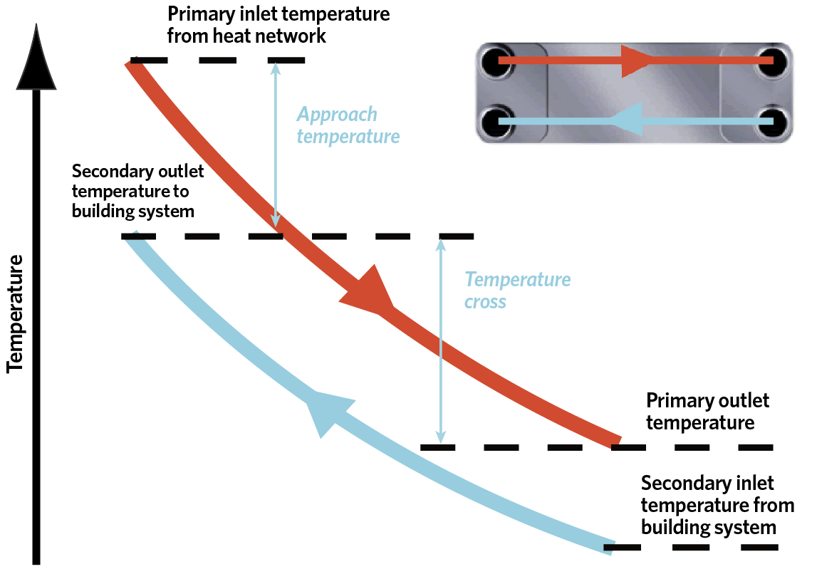
Figure 2: Hydraulic temperatures in a crossflow plate heat exchanger between a heat network and building systems
The Committee on Climate Change estimates that around 18% of UK heat will need to come from heat networks by 2050 if the UK is to meet its carbon targets cost-effectively, and smaller community projects can play an important part of the heat network mix. Heat networks with CHP could be applied anywhere there are multiple heat users, but to make it economically and environmentally effective, such schemes are practically limited to areas with higher density of heat requirement. As discussed in an AECOM report6: ‘The main driver of the cost of a new heat network is the length of underground pipework required. It is therefore preferable to limit the distance between heat customers, by prioritising areas of higher-density development… Previous research into the economics of district heating and CHP has suggested that a threshold of 3,000kW·km-2 can give [appropriate] financial returns… and all potential CHP and district heating schemes should be assessed on a case-by-case basis, taking into account local conditions and heat users, and financial models… and the viability of district heating and CHP schemes depends on what the alternative options are to achieve the required CO2 reductions.’
The ‘correct’ sizing of CHP
The thermal output from CHP may be ‘oversized’ in order to meet the needs of prioritised electricity generation. This could mean that any heat that cannot be usefully employed would need to be ‘rejected’ (or stored), reducing the immediate local efficiency of the system – potentially making a particular installation of CHP a less efficient overall form of generation. An hour-by-hour profile (modelled or using measured data) is the preferred method to examine the heat demands. This is used to identify the requirements for both heat generation and storage, as shown in Figure 3. When less detailed data is available, it is the night/day split – which typically is a function of both heat demand and electricity price – that should always be modelled, as the differences in night and day operational costs and heat demand are normally significant.7
Appropriate thermal load matching is key to the hydraulic design – the output of the selected CHP unit is typically matched to the system’s thermal base load to ensure maximum running hours. By using thermal stores, the operational effectiveness can be maintained across a greater proportion of the time – enabling plant to operate at full thermal output for fewer hours, rather than at part-load, where it would be less efficient. This can also enable the import of cheaper grid electricity – without the need to operate the CHP – through flexible tariffing, while still being able to supply heat (from the store). Appropriate integration with the management controller is essential to ensure the thermal store is effectively loaded and unloaded.
The effectiveness of the hydraulic system operation will be dependent on meeting design temperatures, flowrates and pressure drops.
CP1 recommends that flow and return water temperature difference in the primary heat network under peak demand conditions should normally be greater than 30K for new buildings, to reduce the capital costs of the network. As discussed by Crane8, using a lower return temperature means reduced pipe sizes. He notes that ‘most new heat networks operate at around 5K delta T – commonly 80/75°C because of poor design and/or commissioning. But if a 45°C return temperature can be achieved, along with the specification of pipes two sizes smaller, then heat losses are reduced by 43%, for an unchanged insulation specification’. If return temperatures are reduced to 40°C, it ensures the CHP will operate at a greater efficiency by allowing condensation in flue gases. Orchard9 argues that even lower return temperatures, which are possible when supplying domestic hot-water systems, can provide a significant benefit from the potentially useful energy – and exergy – in the heat supply. Water treatment and filtration, together with continuous commissioning (and maintenance), are required to ensure that the system operates as efficiently as possible.
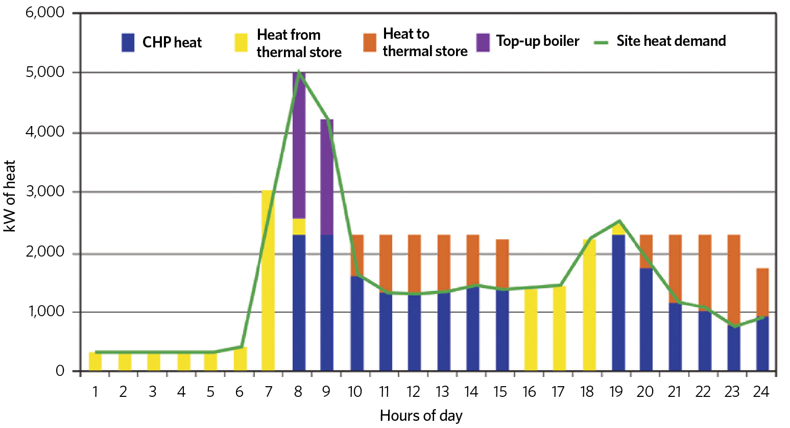
Figure 3: Example of CHP modelling with thermal store over a 24-hour period (Source: CIBSE CP1)
A common recommendation is that the CHP is matched to the base electrical load so that the CHP can run economically for the greatest time. In this mode, it will generate electricity that will be used locally and the consequent heat will be used within the building (or heat network) so that the overall system performs most effectively. As the technologies for electrical battery storage improve – together with the increasing numbers of electric vehicles being connected into a ‘smart’ grid – the opportunities to store electrical power effectively are more feasible, so may disrupt the convention of matching installed capacity with electrical base loads.
An example of alternative thinking is illustrated in Reindl’s recent paper10 on ‘microgrids’ in applications where cooling is required, showing that there are potential benefits from using cool thermal storage charged by running electrically powered chillers at times of excess power availability (as opposed to using current battery technology).
Fundamentally, good-quality electrical network design is, of course, important and that would include the economic sizing of electrical cables, controls and interfacing with the building and network management system. For smaller CHP units – which are not connected to a local ‘microgrid’ – the local DNO will be able to advise if the CHP can be connected to the grid and whether it will accept exported power. In the case of CHP that is matched to electrical base loads, there will be little reason to export electricity to the grid.
Conclusion
There are some significant benefits of including CHP as part of a heat network, such as for a community heating application – greater security, lower transmission losses and grid independence. It is important to consider thermal and electrical demand carefully when sizing the CHP within the scheme, to ensure that both the heat and electrical energy may be usefully employed. Properly designed and operated thermal storage can help to reduce the need for heat rejection and lessen the requirement for the use of boilers to meet peak demand.
As with all building services projects, commissioning is a vital part of the process to ensure operational performance matches the design requirements and expectations. The larger CHP manufacturers have extensive experience in the successful use of CHP in local applications, as well as in more extensive heat networks, and can offer invaluable advice when assessing feasibility.
© Tim Dwyer, 2018.