
As the climate change emergency escalates, pressure will be on owners to decarbonise their buildings faster and further than before. Building services engineers will also have to improve the resilience of buildings to climate change scenarios, including hotter summers.
We have been asked to model the impacts of climate change scenarios on large building portfolios owned by a major pension fund, and we expect this type of work to increase over the next few years.
All aspects of a building will need to be examined and, as window-film technology gets increasingly sophisticated, it will be harder to overlook the contribution it can make to energy efficiency, as well as occupant comfort and wellbeing.
Role of window film
Window physics is determined by the properties of visible light and thermal radiation, which have similar properties. During transmission, they can be reflected (the direction of the wave changes as it moves away from a medium), refracted (the wave direction changes as it passes through a medium), and/or absorbed (see Figure 1).
Window film changes the properties of a pane of glass by reducing the amount of shortwave radiated solar heat and visible light transmitted into a space. It can also reflect longwave radiated heat back into a space, to reduce wintertime heating loads.
Although it is not a new concept, the technology has evolved through complex manufacturing processes, including the use of precious metals.
Figure 1: In this example, relating to direct solar irradiance, 82% is directly transmitted to the space, while 8% is reflected and 10% absorbed (5% each side).1 This equates to a g value of 0.87 (87% total energy transmission). In practice, the amount of solar energy absorbed would not be transferred ‘uniformly’ into each side of the space, as environmental and local factors – including the temperature and weather conditions on the outside face – affect this heat transfer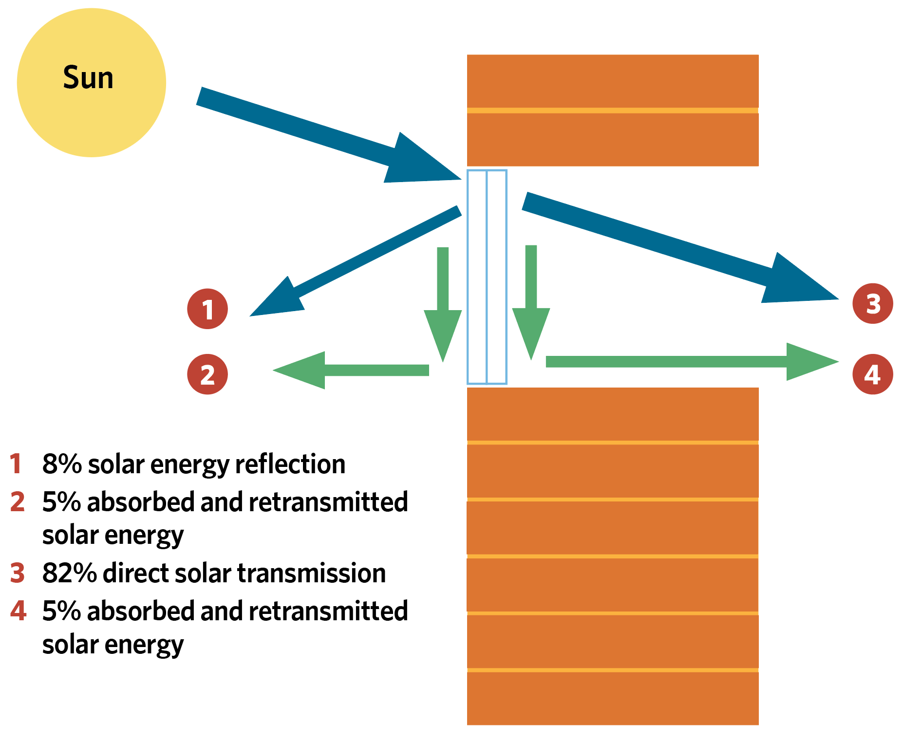
The application of film can change the U and g-values of a window, and reduce visible light and glare. It can be specified through a process of layering, with each layer having different values depending on the specific purpose for which it is required (see Figure 2). These layers serve very specific functions and can be just 45μm thick for internal films, or 75μm for external, and up to a maximum of 325μm for safety films.
Depending on the film type, they can be applied to the outer surface of a pane, the inner surface, or to one of the two middle surfaces of a double-glazed unit, if specified by the manufacturer.
BIM library
It has been difficult to model accurately the benefits of window film, and to ensure a consistent approach to data inputs and modelled outputs. We have been carrying out a research project using a commercially available film, with the aim of creating a BIM library that will allow engineers, architects and modellers to download a type of window film and add it into a model, along with user guides on correct installation.
Various types of modelling software can produce different results, depending on their purpose and default settings. So, to create the BIM library, we had to liaise with the software producers directly, to resolve some of these issues.
Technical challenges
Many energy modellers, even those undertaking dynamic simulation modelling, do not always have an in-depth knowledge of calculating window U and g-values. They will, instead, rely on the templates in their modelling tool(s), or seek to calculate the U or g-value based on information they can glean from various manufacturers, with varying results.
This introduces inconsistency and, therefore, risk to the modelling process, which can have a knock-on effect on the selection and sizing of building services or the interpretation of modelling results – for example, when determining human comfort factors.
To overcome these challenges, it is possible to create mini building information models (BIMs) inside the more complex proprietary modelling systems used by professional energy consultants and engineers. These can be transferred or emailed to other users, and the data imported and exported into other models.
One problem, however, is that these BIMs cannot be transferred between different software systems. For example, it is not possible to open a BIM prepared in EDSL TAS with IES VE or Design Builder, and vice versa. Similarly, it is not possible to transfer the thermal values in a model from Revit or ArchiCAD – often used as design tools – to models used to demonstrate compliance with Building Regulations, Energy Performance Certificates (EPCs), Breeam or Leed credits, or simply design for performance modelling.
We have been carrying out a research project with the aim of creating a BIM library that will allow engineers, architects and modellers to download a type of window film and add it into a model
To try to get modellers thinking more about the potential of window film, we needed to create a library of mini-BIMs compatible with the software used most often for compliance and energy simulation purposes. This is now the primary driver for new-build assets and refurbishments. For example, a design team would not construct a property that might fail Building Regulations or refurbish a property that might earn a poor EPC rating, so this type of modelling has taken precedence over otherwise static datasets, such as IFC Revit files.
One challenge in creating this BIM library was to ensure the modelled input data resulted in the same technical outputs across different vendor tools.
The calculation tool used by LLumar works to the standards produced by the National Fenestration Rating Council (NFRC). This is also used by the Energyplus software used by Design Builder, and we found a close match between the two.
EDSL TAS, however, works to the standards set by the European Committee for Standardisation (CEN), which has different boundary conditions and provides different results. Within IES there are three glazing performance options – CIBSE, EN-ISO and ASHRAE – and the U values differ between them. CIBSE and ASHRAE are more closely aligned to NFRC calculations, while UK compliance uses the EN-ISO methodology (CEN).
These results primarily impacted on U values, while g-values were less affected.
Our solution was to create, within each BIM, the option to use either the NFRC or the CEN calculations, depending for what purpose the model is being used – for example, Breeam, UK compliance, ESOS, design for performance, and so on. This at least allows any modeller easily and consistently to test the impact of window film on a building according to the primary purpose of the model.
MG Tower
There is ‘real world’ evidence of the benefits of window film. A 2011 independent study, by Professor Michele De Carli and his research team at the University of Padua, looked at energy consumption and savings in the MG Tower building in Padua, Italy, before and after the application of a LLumar Helios solar control exterior window film.
The MG Tower is a nine-storey building with more than 1,000m2 of glazing, which was reflecting a lot of light and heat into surrounding buildings.
The study was based on a comprehensive three-year assessment of the building, including 450 days of consecutive monitoring of environmental conditions, investigation of the building’s energy consumption over the three years, and analysis of the energy savings obtained.
A key method used to assess the impact of the installed solar-control film was the development of sophisticated computer simulations for energy use and lighting conditions, as well as economic benefits, CO2 emissions reduction, thermal comfort, and visual comfort. These were calibrated based on data collected from the monitoring phase and from measured local weather conditions.
Detailed calibration was vital to ensure simulations properly represented the behaviour of the building before and after film was applied.
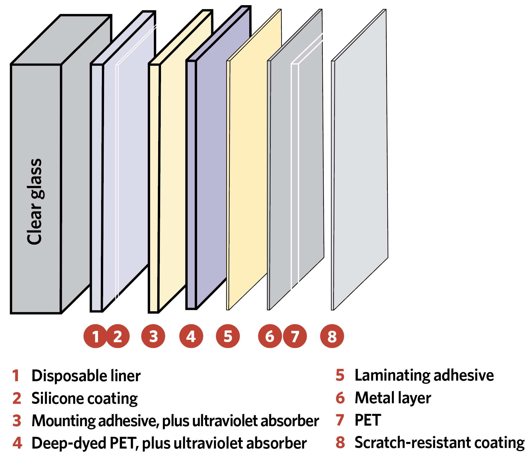
Figure 2: Modern high-performance window film comprises engineered layers. This example shows a six-ply window film structure2
In addition to the quantitative analysis techniques used, occupant surveys were undertaken to identify the perceived impact of the film on the building’s occupants.
The results showed the building reduced its annual CO2 emissions by 46 tonnes after the application of the window film, and there was a return on investment within four years, largely because of the reduced need for air conditioning cooling.
The window film reduced indoor temperatures by up to 5°C when cooling plant had been switched off. The reduced need for air conditioning and glare reduction increased occupant satisfaction significantly, and the research team concluded that this improved productivity by ¤40 per employee per cooling month.3
Modern buildings have numerous windows, many of which cannot be opened. They require complex systems to ensure comfortable temperatures for occupants throughout the seasons. Innovations in window film technology will, therefore, be an important element for engineers who are looking for technologies to reduce the environmental and thermal impact of their buildings.
- The BIM library can be accessed by contacting prossouw@eastman.com
- Andrew Cooper is director at Evora Edge, the technical engineering division of a global sustainability consultancy.
References:
- Andrew Cooper, Module 14 (Building physics and thermal comfort) of the Energy Institute’s Level 2 Energy Management course.
- Source Performance film for glass – taken from a CIBSE CPD presentation by Eastman.
- Case study: Eastman Performance Films commissioned the University of Padua to conduct an independent study of the effects of using LLumar solar control window films on the MG Tower.