
Examples of the application of fabric- or textile-based air distribution stretch back into the mid-20th century, where simple, inflating cotton bags (or ‘socks’) were attached to the end of metal spigots to provide a means of supplying large amounts of ventilation air. Although, originally, applications tended towards industrial locations where the lightweight, machine-washable ducts were particularly attractive, such as food preparation areas, slaughterhouses and laboratories (see Figure 1), they have since seen wider adoption in commercial and industrial installations, such as offices, workshops, schools, shops and showrooms.
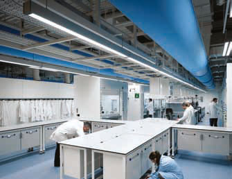
Figure 1: Example of a laboratory using a low impulse permeable textile half circular (‘D’-shaped) ventilation system
Despite their increasingly widespread use, there is little design guidance from CIBSE or ASHRAE. However, several manufacturers – many of whom evolved in Europe – have developed respectable design and installation guides as part of their sales offering, with each system requiring individual design, dependent on the room characteristics, supply air volumes and temperatures.
The cotton used in the early applications was quickly found to absorb water and, owing to its organic nature, potentially harbour bacteria and moulds, so it was quickly replaced by polyester and oil-based synthetic fibre that became widely available in the 1950s. The polyester employed is a UV and crease-resistant material that can be coloured, providing a robust, flexible fabric that, when woven with other specific yarns, make it fire retardant. At the end of the useful life, the fibres can also be re-processed into recycled polyester materials.
Textile ducting is applied using both permeable and non-permeable materials. Permeable materials may be categorised by their dust-holding capacity. This is not to infer that the ducts should be used as a filter – textile-based systems require filtration in the air handling unit like more traditional metal duct systems. However, some particulate matter will pass into the supply air – the fabric’s dust-holding capacity and the quality of the centralised filtration will influence the frequency of cleaning. High dust capacity (HDC) materials are made of staple fibre yarns capable of carrying a large amount of dust without blocking the airflow through the material. Low dust capacity (LDC) materials are typically woven of multifilament warp yarns. These fibres are plain and smooth, with a small surface compared to that of the staple yarns. In weft direction (crosswise), the same staple yarns are used as for the HDC fabric; however, the weaving-method is a more simple cotton bond, with a much smaller surface than that of the HDC fabric. HDC materials will hold more dust and increase the period between washing intervals, along with helping to minimise any increase in pressure loss.
Air distribution with textile-based ventilation systems
The air distribution principle used for a simple textile-based ventilation system is fundamentally different from that of a conventional ventilation system equipped with metal ducting and discreet diffusers. Uncoated textile-based systems use permeable fabrics to distribute the air into the room, diffusing through the surface area of the material, enabling air to enter the room at a low velocity (as in Figure 2) – sometimes termed ‘low impulse’ systems. Directed systems use non-permeable fabric materials (coated in a self-extinguishing and flame-retardant plastic coating), with the addition of nozzles and/or laser cut holes to project and distribute the air supply to the room at higher velocities, sometimes termed ‘high impulse’ systems (Figure 3). There are also hybrid systems that use a mix of the permeable material for diffusion and additional openings for projection and further distribution of the air (Figure 4).
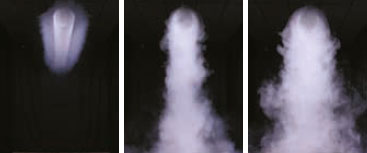
Figure 2: Circular permeable textile ‘low impulse’ supply – cooling ΔT of 0K, >5K, <3K
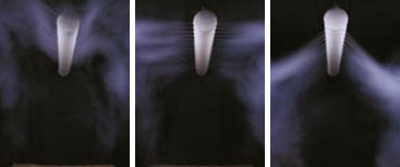
Figure 3: Circular non-permeable fabric ‘high impulse’ supply ducts with directed nozzles
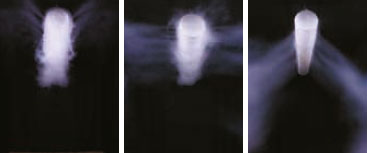
Figure 4: Circular permeable textile ducts with the addition of directed nozzles for diffusion and projection
‘Low impulse’ supply systems
The air distribution principle for these systems is often based on displacement ventilation principles, where the air is supplied at a slightly lower temperature than the room air. Because of the difference in density, the cooled supply air being heavier than the warmer room air, the supply air continues moving towards the floor. As with other displacement systems, heat from sources – such as people, equipment and solar gain – generates convection currents, resulting in the air being displaced, so moving heat and pollutants away from the occupied zone to be extracted at high level. Supplying air at a low velocity is suitable for cooling or for distributing large volumes of air at a temperature similar to that of the room air. High air-change rates (and associated cooling) can be achieved with low terminal velocities in the occupied area, owing to the air being discharged over the entire surface of the ducting. For example, each metre run can provide about 700 watts-cooling using a room/supply ?T of 3K in an office-type application (approximately 200 W cooling per m2 floor area) – the diameter of the duct being determined by its capacity to convey the total flowrate for that particular branch (using manufacturers’ data sheets).
In permeable low impulse supply systems, the textile surface is effectively a fine mesh, allowing the supply air to pass through the surface at a low, uniform discharge velocity (normally less than 0.1 m·s-1). The discharge velocity should be kept below (approximately) 0.40-0.50 m·s-1, as beyond this the room air will start to entrain and mix with the low temperature supply airflow. The noise generated by this low-velocity supply is commensurately low and, when appropriately designed and installed, can be used where noise levels down to 20 dBA are required. Since the surface of the material is continuously ‘washed’ through by the diffusing supply air, the surface of the material does not exhibit condensation, so allowing supply air at a temperature below the dew point of the room air.
Such low-velocity systems are unsuitablefor heating applications, as warmer supply air will settle at high level and is likely to ‘short circuit’ back into the extract system.
‘High impulse’ supply systems
These rely on purpose-made openings in the non-permeable duct material to provide jets of supply air. These may be in the form of small holes or slots (factory cut and finished), arranged in specific locations and groupings in the textile duct, or by using nozzles fixed into the fabric that allow both area and direction of the air jet to be more closely controlled.
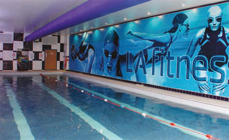
Figure 5: Example of a swimming pool using a high impulse non-permeable circular ventilation system with 4.5 mm holes
Ducts with many small holes (jets) in the textile result in large induction of room air, so the velocity is reduced more quickly (and the throw reduced) compared to nozzle systems (Figure 5). Adding nozzles to the duct increases the supply options, so that systems may be manufactured to meet very specific air distribution needs (Figure 6). So, for example, systems may be produced for industrial areas that have nozzles to ‘air wash’ the soffit to remove condensation, while other nozzles are oriented to satisfy the comfort needs of the occupants below. The air may be directed along adjacent surfaces, employing the ‘coanda effect’ to increase the effective throw.
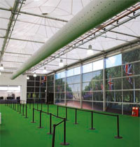
Figure 6: Olympic temporary portal at Heathrow Airport, using a high impulse non-permeable circular ventilation system with nozzle diffusers
These systems will provide mixing ventilation, with the air being delivered outside the occupied zone at high velocity. So, for example, using plain holes of approximately 4.5 mm diameter will deliver air at 6 m·s-1 with an internal duct static pressure of 50 Pa, and 16 m·s-1 at 200 Pa duct pressure. The distribution pattern of the holes will determine the throw and spread. To provide more control of the design of the supply air pattern, nozzles (typically 12-60 mm diameter) may be selectively factory fitted (Figure 7) according to the application, giving velocities of around 8 m·s-1 (at 50 Pa) to 16 m·s-1 (at 200 Pa) (nozzle size being determined by duct mounting height and the throws required for the room). Throws would typically be from a few metres, using 12 mm nozzles, to 25 m-plus with larger 60 mm nozzles, for both heating and cooling.
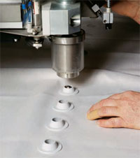
Figure 7: Nozzles added to the textile ducting during the manufacturing process
The velocity of the air moving through the room will reduce the local air static pressure and entrain air from the room volume (where there is a higher static pressure). As the jet draws in more room air, just as with ‘traditional’ air diffusion devices, the velocity of the air will reduce and, if appropriately sized, the supply air will be completely mixed with the room air before it reaches the occupied zone and the air velocity has dropped to a reasonable value.
A textile-based high impulse supply system may be used for cooling systems, tempered ventilation and heating applications, since the supply air is delivered with sufficient velocity to allow the air to mix with the room air independent of the temperature difference between the supply and the room air. Just as with ‘traditional’ diffusers, these systems may be characterised by ‘throw’ and ‘spread’. Unlike low impulse supply systems, the location of the exhaust has only a minor influence on room air distribution.
Air travelling through the coated, nonpermeable flexible ductwork must be above the dew point of adjacent room air, otherwise condensation will form on the duct’s surface.
Occupied zone
The occupied zone is the target volume where the system aims to maintain the required conditions. It is by no means fixed but will vary from one project to another, depending on use of the space. Typically, the occupied zone is defined as the zone from the floor up to a height of 1.8 m where occupants are in a standing position, and up to 1.1 m for people who are seated. The term ‘near zone’ may be used in the case of horizontal low velocity supply systems (Figure 8), to indicate the zone under the textile ducting where there is an appreciable risk of a ‘cold downdraught’.
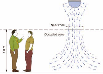
Figure 8: The near zone for a horizontal low impulse supply system – the volume that is not suitable for occupied use
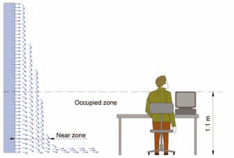
Figure 9: The near zone for a vertical low impulse supply system – the volume that is not suitable for occupied use
For vertically-mounted systems, the near zone is taken to be the local zone around the duct where the air velocity is greater than that required for occupant comfort (Figure 9).
Installation
The duct (Figure 10) is typically suspended using aluminium track or point systems, designed to allow speedy installation and removal (for cleaning), as well as ensuring that the system maintains its shape and appearance (Figure 11). Since textile ductwork relies on the pressure of the air inside the duct to maintain its consistent shape, specific care should be taken to ensure that there are appropriate pressures – not only to move the air from the duct into the conditioned space but also to minimise the effect of pressure perturbations (or ‘fluttering’).
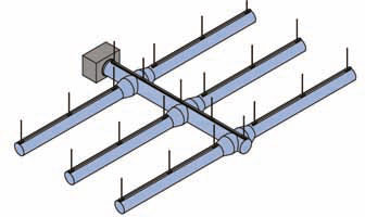
Figure 10: Example of a duct system layout
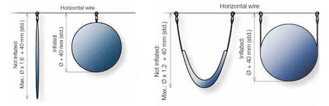
Figure 11: Example of single and double suspension, and how the duct will look with and without air flow
The sections of duct are connected with ‘zip’-style fasteners, allowing easily manageable sections for installation and ready access. Abrupt changes in direction and interference from framework can cause mis-shaping, vibration and noise in the fabric. However, radial bends, angled sections, dog-legs, and complicated shapes can be made in textile ducting – it is not restricted to straight runs.
As the air travels through the constant diameter of the duct, its velocity will drop as the air is diffused into the space. By virtue of static regain, the static pressure will tend to rise (in spite of the frictional pressure drop), and this should be considered when designing systems.
The noise produced by textile ducting is very low in comparison to metal systems, and so higher duct velocities of 6-7 m/s are possible while still achieving low noise ratings. It is important to note that there is little sound absorption in the material, so attenuation will still be needed to remove noise from the central distribution system and air handling, as with a metal-ducted system.
© Tim Dwyer 2013
This article was produced with the input of Mark Bailey, with reference material and all images supplied by KE Fibertec UK.