
Variable refrigerant flow (VRF) systems are a refined and more flexible development of the mature technology that has been applied in ‘split’ direct expansion (DX) and heat pump systems. As well as providing distributed, temperature-controlled room units, by applying reversible heat pump technology VRF can simultaneously shift heating and cooling around the building, so reducing overall energy use. This CPD will consider the development of the VRF system and explore the newer implementations capable of efficiently producing directly useable hot water.
Reduced area
Compared with a ducted air system, heat being transferred around a building through refrigerant pipework requires a fraction of the area, in terms of ‘conduit’ size, to provide similar heating or cooling to a space. For example a load of 5kW would require a circular air duct of around 350mm compared with a pair of refrigerant pipes of less than 15mm diameter (plus insulation for both the duct and the pipes). Normally, there would also be a need for ventilation air where the volume flow of ducted air would be related to the fresh air requirement. This is likely to be far less than the air flow that would be required to meet the whole heating or cooling load in the space and, if required, is often supplied using a dedicated outdoor air system (DOAS) that may also enable closer humidification control.
The use of ‘split’ DX systems is common across the globe due to both the reduced space required for the installation of ductwork and the relative simplicity of installation. (Note: direct expansion, or DX, refers to the direct expansion of refrigerant for cooling.) Often, DX systems comprise a single room unit attached to a single external ‘condensing’ unit (either simply ‘through-the-wall’ or with a short length of pipework connecting the two units). Recent ‘multi-split’ DX systems – where several internal units are individually connected to a single external ‘condensing’ unit – are almost all powered through a variable flow compressor that will accommodate changes in the sum of the demands from the multiple connected room units. These are limited to providing either cooling, or – in the case of a reversible ‘heat pump’ system – heating across all the units at any one time. The reach of a traditional multi-split system would typically be limited to less than 100 metres of total pipe run (so, for example, if there were four internal units they could each be 12.5m metres away from the external unit).
Evolution
Over the last 15 years, variable flow systems have evolved from simple multi-splits so that, through more sophisticated control mechanisms, they can extend to supply dozens of indoor units connected with several hundred metres of pipework to one or more outdoor units using variable flow (controlled by the demands at the room unit). They can also supply terminal units spread over 100m vertically from the outdoor unit. Rather than use separate gas and liquid pipe runs to each and every unit, these systems use a single pair (or trio) of refrigeration pipes that can serve many units (and sub groups), and are known as VRF systems.
Each outdoor unit would typically provide up to about 200kW cooling capacity and the distributed indoor units up to 35kW each unit. The outdoor unit will commonly have multiple compressors, and at least one of these would be a variable capacity device. The compressors would normally be rotary or scroll compressors that inherently have little vibration and are controllable through modulating speed or digitally altering the geometry.
The appearance of the indoor units is similar to that of a traditional (water based) fan coil unit and they are similarly flexible with their positioning in the space. As with any coil that can operate below the dew point temperature of the room air, they should always be fitted with appropriate condensation drains. The room units will contain a fan, a refrigerant coil and controls providing both autonomous and integrated control operation. The room unit’s temperature will be set by the condition of the refrigerant running through the coil in the unit, in response to room – or zone – temperature sensors.
The specific controls will be determined by the manufacturer’s particular arrangements, but they would typically enable temperature control, fan speed control and, if included, dampers to allow fresh air supply. However, the headline operational benefit of VRF is through its integrated operation with both the other terminal units and the outdoor compressor unit. All will be connected through a common control system, which may itself be linked in to a central building management system and protocols such as BACNet and LONworks.
There are number of configurations offered that include single-mode systems (offering either heating or cooling concurrently to all the indoor units, which may be simply referred to as ‘heat pump’ VRF systems) and dual-mode systems employing two or three refrigerant pipes sequentially, serving units that individually can concurrently provide heating or cooling (these are frequently known as ‘heat recovery’ VRF systems).
Operationally, single-mode VRF systems will be similar to traditional multi-splits (aside from their ability to service more extensive systems). They can take advantage of the diversity of the timing of loads (for example, the temporal variation in peak cooling required for east- and west-facing office zones) to reduce the main system size (just as VAV does in ducted air systems). While operating in heating mode, all the internal coils will be acting as condensers, and the heating will be controlled by the electronic ‘expansion’ valve (sometimes referred to as a ‘linear expansion valve’) metering the flow. This will maintain an appropriate level of sub cooling (and so coil temperature) in the refrigerant as it leaves the room coil to return via the common return pipe to the external condensing unit. The electronic expansion valve in the external unit will, in turn, act to maintain an appropriate degree of superheat at the compressor intake, while the flow of refrigerant is modulated to meet the flow demands of all the distributed units.
Conversely, when operating as cooling devices the internal units would function as evaporators, and the degree of cooling provided will be controlled through the local expansion valve maintaining appropriate superheat (and so coil temperature) at the exit of the local coil.
Where there are concurrent loads for heating and cooling in different zones, dual- mode (heat recovery) systems allow heat to be moved around the building between areas that require heat and those that require cooling. Heat would effectively be moved from areas that require cooling to those that require heating without the need for the refrigerant to pass through the condenser/evaporator coil in the external unit. The external compressor will still operate (to provide the compression for the cycle), and will adjust capacity to satisfy the total cooling being delivered by the sum of the individual units.
The room units contain the same coils and fans as for single-mode systems. However, by applying appropriate controls and some sophisticated piping arrangements, they allow concurrent heating and cooling within separate room units.
Each of the indoor units is individually controlled, maintaining a required refrigerant flow to meet the load requirements by the use of electronic expansion valves (EEV), and the sum of all the flows is matched by modulation of the compressor output. The EEV also allows each individual unit to be isolated when an area is unoccupied or no conditioning is required.
In two-pipe heat recovery systems, a control unit local to a number of internal units provides a redirection of refrigerant between internal units so that some can act as evaporators providing cooling while, concurrently, others may act as condensers providing heating. The external unit will provide the compression to power the refrigeration cycle and, in some circumstances, if the cooling load of individual units matches the heating load of other units (plus the heat of compression from the external unit), the external coil will be bypassed and so the internal unit coils will be providing the complete evaporation and condensation elements in the refrigeration process.
In a three-pipe system, as shown in Figure 1, onepipewouldbetheliquidline(as connected to the outlet of a condenser); one a high-pressure vapour line (effectively at the pressure of the compressor discharge); and one a low-pressure vapour line (effectively operating at the pressure at the inlet to the compressor).
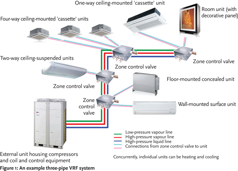
Figure 1: An example three-pipe VRF system
When cooling is required, a control unit would open the unit’s coil to the liquid line (through the expansion valve) and provide the outlet into the low-pressure vapour line, so acting as an evaporator. For heating, the coil would be opened to the high-pressure vapour line and the outlet to the liquid line, so acting as a condenser. In both cases, the amount of cooling or heating would be controlled by the EEV to produce the required degree of superheat, or sub-cooling, respectively.
Where there is an appropriate balance of heating and cooling loads across a building (the ‘sweet spot’ typically being where the cooling amounts to 40%1 of the total building load), manufacturers show that there is potential to operate with an effective coefficient of performance (COP) in excess of seven (as shown in Figure 2). This COP would not prevail throughout the whole season’s operation, being dependent on both the external conditions and the load balance.
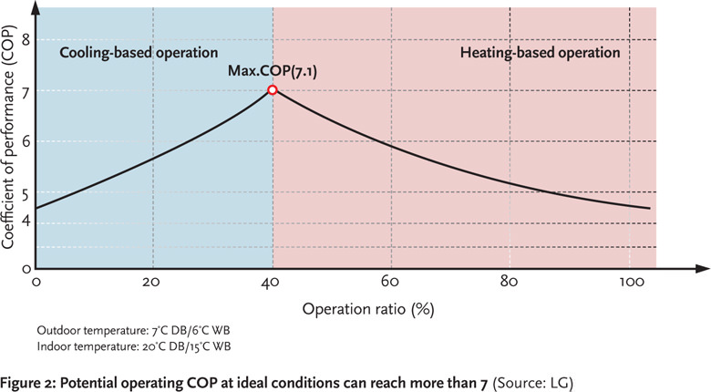
Figure 2: Potential operating COP at ideal conditions can reach more than 7 (Source: LG)
In a heat recovery VRF system, there are opportunities to capture heat not required for space heating that may otherwise be rejected, and use it productively, for example, in a thermal store or to generate domestic hot water. Similarly, there is potential to use the heat pump facility of the VRF to supply heat for hot water generation.
The thermodynamics of the vapour compression refrigeration cycle will mean that when using a refrigerant, such as the commonly used R410A, the maximum temperature that can be efficiently generated is about 50°C. This is usable for underfloor heating applications and potentially some ‘low temperature’ heat emitters, as well as preheating for domestic water.
But as the difference between source (for example, the outdoor or room air) and the required target temperature (for example, the hot water store) increases, so does the compressor pressure ratio, and this will reduce the capacity of the system, alongside a falling system COP.
Hot water generation
A number of methods have been identified to lift the upper temperatures of the cycle specifically for building services applications. A method being offered by several VRF manufacturers is to provide a cascade arrangement, where a second refrigeration cycle (using R134a refrigerant) uses the heat from a condenser in the VRF system to provide heat for the R134a evaporator. This cascaded system (Figure 3) can provide a useful solution where the demand for heat (for example in hot water storage) can absorb the variations in the space heating demands from the building, so more fully utilising the heat generated to produce the cooling required by the remainder of the installation.
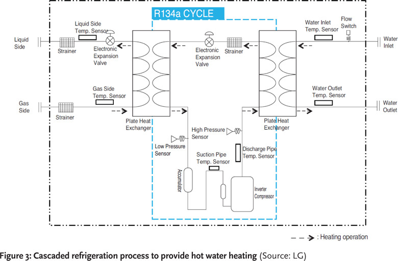
Figure 3: Cascaded refrigeration process to provide hot water heating (Source: LG)
System considerations
As with any air source heat pump, the outside coils are likely to accumulate frost when the system is in heating mode (since the outside coil is acting as an evaporator at low temperature). This may be cleared via a number of automatic mechanisms, depending on the number and layout of external coils – though any defrost cycle will affect the system performance (and ‘derate’ the installed capacity). However, the effect of the cycle is unlikely to be noticeable in the room units. When there are multiple external units, such defrost cycles can be effectively sequenced while still maintaining heating to the internal units.
One of the developments that enable VRF is the control mechanism to maintain the lubricating oils in the compressor. Recovery of oil entrained in the refrigerant is principally achieved by capturing the oil before it enters the main distribution pipework. However, there will always be some carryover of lubrication oil into refrigerant flow, and this is recovered through a automatic dedicated cycle (lasting a few minutes), where the electronic expansion valves in individual units are automatically manipulated (they are all linked via the system’s control network) and the compressor operates to pump the oil from the system back to the outside unit.
There is likely to be a significant network of insulated copper refrigerant piping to serve a VRF-based system, including many brazed joints and some flared connections. The design for the refrigerant network must comply with the requirements of safety standards (such as BS EN 378 Refrigerating systems and heat pumps – Safety and environmental requirements and ASHRAE Standard 15 – Safety Standard for Refrigeration Systems). Similarly, the installation must be installed and operated to comply with the current standards, most notably the ‘F-Gas’ regulations.2
The cost of installing a VRF system is similar to that of a three- or four-pipe water-based fan-coil system.3 Particularly where there are opportunities for heat recovery, which may include using excess space heat for low and higher temperature hot water production, this electrically-powered system can be both straightforward and flexible to install and operate, and provide competitive seasonal efficiencies and operating costs.
© Tim Dwyer, 2013
References:
- LG UK – Heating with Air Conditioners to reduce carbon emissions, Powerpoint presentation, 2013.
- (In Britain) The Fluorinated Greenhouse Gases Regulations 2009, The Ozone-Depleting Substances (Qualifications) Regulations 2009.
- ASHRAE Handbook 2012 – HVAV Systems and Equipment, page 18.3