Carbon dioxide (R–744) is regaining its place in the refrigeration world, having almost disappeared from widespread use in building services in the early days of air conditioning. Driven by environmental concerns, legislation1 is requiring increased adoption of ‘alternative’ refrigerants, of which CO2 is one. However, the development of transcritical CO2 systems also provides opportunities for using this largely benign, naturally occurring chemical to power air-sourced heat pumps that can effectively produce temperatures suitable for domestic hot water.
The rise and fall of CO2
The resurgence of CO2 is due to its environmental credibility as a ‘natural refrigerant’, but it is also non-flammable and has thermodynamic properties that give smaller volumetric refrigerant flowrates compared to the well- established halocarbon systems. It also has the benefit of being categorised as non-toxic (although it is an asphyxiant gas).
CO2 as a gas makes up more than 390 ppm (0.039% by volume) of the earth’s atmosphere – one of the more significant gases. The ease by which it can be produced led to its early application in refrigeration in the mid 1800s, and it was subsequently applied widely in food refrigeration.
The use of CO2 refrigeration in sea transport enabled the liberalisation of the world fresh food market, and it reigned until the middle of the 1940s, when newly invented synthetic halocarbons became popular owing to their higher efficiencies and lower operating pressures. These displaced CO2 as the favoured refrigerant, so that by 1960 CO2 was rarely used in marine applications2.
Its use continued in ‘cascade systems’ for industrial and process applications, where it provides low temperature refrigeration ‘cascaded’ with a higher temperature cycle (employing another refrigerant) to provide final heat rejection. However, over the last 40 years, the environmental consequences of chlorofluorocarbons (CFCs) and, subsequently, hydrochlorofluorocarbon (HCFCs) and, then, the realisation of the global warming penalty of hydrofluorocarbons (HFCs) has turned the focus back to natural occurring refrigerants such as CO2, ammonia, and the hydrocarbons.
The many personas of CO2
CO2 is well known both to the general public and engineers. Atmospheric CO2 is closely associated with climate change – providing about 60% of the enhanced greenhouse effect – where relatively small changes in global concentrations are linked with rises in global temperatures. The global warming potential (GWP) of CO2 is relatively low compared with synthetic refrigerants such as R134a, which has a GWP 1,300 times that of CO2, or even the recently developed ‘environmentally friendly’ refrigerants such as HFO–1234yf, with a GWP of 4. By comparison, naturally produced methane has a GWP of 25.
CO2 is produced by the combustion of coal or hydrocarbons, through respiration, by fermentation, via plant decay, plus it is released from the earth’s core through openings such as springs and volcanoes, and produced from acidic water on carbonated material such as limestone. Naturally-occurring CO2 emissions are roughly balanced by both photosynthesis in plants and absorption at the surface of the world’s water masses. Atmospheric CO2 is thought to have risen about 40% since the start of the industrial revolution.
Internal environmental CO2 levels (in the air) are typically considered to be at around 1,000 ppm and above, although many studies have measured long-term values that, in practice, are much higher, with the attendant concerns about the effect of this on mental performance and physical health3.
The phases of CO2 are shown in Figure 1. The triple point, at -56.6°C and 0.52MPa, indicates the point where CO2 may co- exist as solid, liquid and gas – a slight perturbation in pressure or temperature can switch the state instantaneously. Above the critical point, 31.1°C at a pressure of 7.36MPa, there is no separated liquid or vapour – it is a homogenous ‘supercritical’ fluid. Above this point, the latent heat of vaporisation is zero – it does not exist. If the supercritical fluid was extremely compressed (far beyond anything in the commercial HVAC world) it would form a solid.
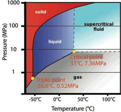
Figure 1: The phases of carbon dioxide
CO2 may be distributed as a solid (created by pressurising and refrigerating carbon dioxide rich gases), and as it sublimes to a gas at -78.5° C (at standard atmospheric pressure) it will consistently provide a source of cooling (but with little opportunity to recycle the gas). Thus, it provides a portable source of cooling that requires no equipment at point of use. (It is also used theatrically as ‘dry ice’.) Each kilogram of solid CO2 will absorb 571 kJ from its surroundings as it sublimes into a vapour. It is more often distributed as a liquid in pressure vessels and is used for industrial processes, fire extinguishers, in the food industry and – increasingly – refrigeration. The cost of CO2 is very low compared with other manufactured refrigerants.
CO2 in transcritical refrigeration
The outlines for both simple R134a (subcritical) and CO2 (transcritical) systems are shown on the combined pressure enthalpy diagrams in Figure 2 – the term ‘transcritical’ simply meaning that the cycle passes across the critical point. Applications of transcritical refrigeration have taken off in the last 20 years, particularly with small refrigeration systems – initially for automotive and small marine applications – that are generally acknowledged to have developed from work undertaken by Gustav Lorentzen in the late 1980s. Conveniently, the low critical temperature sits in the middle of the ranges of temperature that are frequently found in HVAC and R applications.
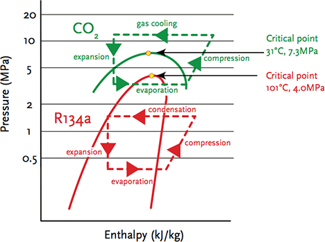
Figure 2: A basic comparison of simple refrigeration cycles – subcritical R134a refrigeration and transcritical CO2 cycle
In transcritical refrigeration cycles, CO2 operates at much higher pressures than traditional HFC and ammonia systems. Modern manufacturing methods have enabled the production of low-cost components capable of operating at the high pressures required for CO2 refrigeration. This includes small domestic units, heat pumps, supermarket applications, and, to a lesser extent, industrial applications. Smaller CO2 systems tend to use unitary transcritical systems, whereas larger, commercial and industrial systems are more likely to employ CO2 as a low temperature refrigerant in cascade systems, together with other refrigerants such as ammonia being used as the high temperature refrigerant. There have been developments in small scroll compressors and reciprocating compressors specifically for transcritical CO2 systems. CO2 has a higher volumetric refrigeration capacity than traditional refrigerants (so requiring less displacement) but at much higher pressure differentials. The reduced volume flows of the refrigerant provides opportunities for smaller components.
CO2 can also be used as a direct refrigerant, where liquid CO2 is simply pumped under pressure to an evaporator supplying the cooling load, with the vaporised CO2 then passed through a low temperature heat exchanger (still at high pressure) and condensed, ready to be recirculated to the load.
Subcritical and transcritical cycles
Looking at Figure 2, the R134a cycle has the evaporating process starting off bottom left, where the low temperature refrigerant is a mix of vapour and liquid. As the refrigerant gains heat from the surrounding cooling load (or heat source for heat pump), its enthalpy rises with the refrigerant at constant pressure, until it becomes a superheated gas at the intake of the compressor. The compressor increases the pressure, also adding heat to the refrigerant, and consuming power to drive the motor. The hot, high-pressure, superheated gas enters the condenser, where heat is rejected (or, in a heat pump, passed to the heat transfer medium) and the gas reverts back to a liquid. The warm, high-pressure liquid (often subcooled) passes through a pressure-reducing device (an expansion device) at constant enthalpy. The whole cycle is below the critical point, so is known as a ‘subcritical’ process. The expansion device is designed primarily to ensure that superheated gas enters the compressor by sensing the condition of the low-pressure refrigerant leaving the evaporator to control the flow.
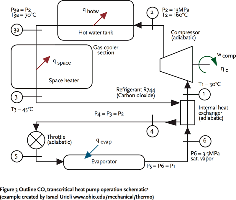
Figure 3 Outline CO2 transcritical heat pump operation schematic4 (example created by Israel Urieli www.ohio.edu/mechanical/thermo)
For a transcritical CO2 cycle, the process does not look greatly different; however, the heat rejection occurs above the critical point and the temperature reduces while the CO2 remains a gas, and there is no condensation. Both the absolute operating pressures and the range of pressures is far higher than for halocarbon systems. By the system – and specifically the ‘gas cooler’ – rejecting heat above the critical temperature, it allows the CO2 system to operate so that it can provide heat at an exergy that is useful for heating domestic hot water (while the evaporator is operating at low temperatures suitable for cooling, or for drawing heat from low- temperature outdoor air in a heat pump application).
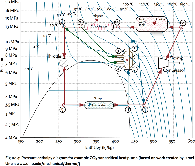
Figure 4: Pressure enthalpy diagram for example CO2 transcritical heat pump (based on work created by Israel Urieli: www.ohio.edu/mechanical/thermo)
At its simplest, the pressure reduction is undertaken using a high-pressure expansion valve (HPEV) that controls the flow of refrigerant based on the pressure in the heat rejection (gas cooler) part of the cycle. In principle, the HPEV is normally held closed by a spring that works in opposition to the pressure in the gas cooler. There are enhancements that have been applied to the expansion process to improve the seasonal performance such as using two stages of expansion, with an intermediate liquid receiver with a direct vapour feed into the end of the evaporator process. A liquid receiver is often variously used (sometimes in association with an additional expansion valve to prevent damaging liquid CO2 entering the compressor) at the start or end of the evaporator to provide a buffer that allows the metering of the refrigerant to maintain optimum design pressures in the gas cooler.
The efficiency of the system is closely related to optimising the lift provided by the compressor and the temperature at the outlet of the gas cooler – commercially available systems use tuned control algorithms to ensure seasonal performance is maximised. A heat exchanger is often used to exchange heat between the relatively hot discharge from the gas cooler and the cold discharge from the evaporator. An example application is shown in figure 4 for a heat pump feeding domestic hot water and space heating. In the example, the evaporator is operating at 0°C. To ensure good performance, the heating load – in this case, the space heating – should be designed to work on a wide temperature drop, allowing the gas cooler to work most effectively and provide the greatest opportunity for the evaporator to absorb heat from the outdoor heat source. Systems are available using hermetic and semi- hermetic multistage CO2 compressors to match the range of loads suitable for building services engineering. For larger systems, such as supermarkets, CO2 transcritical systems are now frequently used to provide high temperature loads in conjunction with lower temperature, subcritical CO2 systems.
© Tim Dwyer 2012
Further reading:
For an introduction to the basic refrigeration process, see Refrigeration – inside the box, CIBSE Journal CPD March 2009.
There is an excellent presentation at www.phi-usa.com/Papers/CO2-presentation-LAM-2003-06.pdf that looks at the comparative attributes of CO2.
CO2 – a refrigerant from the past with prospects of being one of the main refrigerants in the future, by Nekså, P., provides both an historical perspective and description of key components (freely available – find via a web search engine).
For a historical perspective, see Pearson, A., Carbon dioxide—new uses for an old refrigerant, International Journal of Refrigeration, Volume 28, Issue 8, December 2005.
For safe commissioning and operation of CO2 systems, the pre-eminent reference is the Institute of Refrigeration’s (IoR) Safety Code Of Practice for Refrigerating Systems Utilising Carbon Dioxide Refrigerant.
References:
- ec.europa.eu/clima/policies/f-gas/index_en.htm – accessed 11 November 2012.
- Forbes Pearson, S., Report on Lloyds Register of Shipping, 1970.
- Impact of CO2 on human decision-making and productivity, Satish, U., et al., Sunny Upstate Medical University, CARTI Presentations, April 2010.
- www.ohio.edu/mechanical/thermo/Applied/Chapt.7_11/Chapter9.html – accessed 11 November 2012.