In the August CPD, the concept of static, velocity and potential pressures combining to give total pressure was described. Total pressure will always reduce as a fluid passes along a conduit (pipe/duct) – this is normally calculated as a drop in static pressure. Potential pressure will be related to the change in height as the conduit runs through the building and, although significant for liquid systems (with high densities), it is less so with air systems. The speed of the flowing fluid will directly affect the velocity pressure (in a square law relationship), and the static pressure will in turn compensate for any rise or fall in velocity pressure (the latter frequently referred to as ‘static regain’).
This CPD will consider the application of these concepts to examine how ducted air system designs might be adjusted to reduce their energy consumption.
CIBSE Guide Bi asserts that some 8% of electrical consumption in air conditioned and mechanically ventilated buildings is likely to be due to the motors powering the fans. This absolute fan energy use may well have reduced for new buildings in the intervening years since publication of Guide B, as the requirements of the Building Regulations to moderate building cooling loads have strengthened and the maximum allowable power consumed by fan systems have become more stringent. Nonetheless, contribution to energy use and the resulting carbon footprint will be significant.
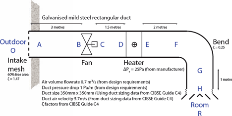
Figure 1: Simple ventilation system.
Taking a very simplified air handling system, as in Figure 1, pressure drop can be established using the principles outlined in the August CPD. (More detailed commentary and rationale is given in the appendices of CIBSE Guide B, Section 3, as well as in the excellent examples of the CIBSE Guide to HVAC Building Services Calculationsii.) The data to determine the pressure drop through the rectangular galvanised steel ductwork and the individual fittings may be obtained from CIBSE Guide Ciii or ASHRAE Fundamentals, Chapter 21iv.
There are three principal methods commonly used to size ducting:
- ‘Constant pressure drop’ – commonly used, easily applied method for low pressure (+/- 500Pa) comfort ventilation systems – particularly for final distribution ductwork and constant volume systems;
- ‘Constant velocity’ – particularly useful where there is a need to maintain a minimum velocity (for example, to convey particulate matter along ducts); and
- ‘Static regain’ – a more complicated iterative method (although readily computerised) that can provide better stability, particularly for VAV systems and main distribution ductwork.
Although any one of them could be used, in this example the more frequently employed ‘constant pressure drop’ method will be applied for a small single office ventilation system. The actual value for the static pressure drop (per metre) used as the constant value will be determined by the application – larger values will not only consume more power but are also likely to cause more noise with the smaller duct sizes and the resulting higher velocities. For the purposes of this example, the time-honoured value of 1Pa/m will be used. This is a value that many years of experience has apparently proved to be a good compromise between the demands to keep ducts small, so as to limit space needs and keep capital costs low, and the higher noise and operating costs that arise from smaller ducts. (Conveniently, it also has a nearly equivalent value in the IP system of 0.1 inches wg per 100 feet ductwork.) Guide B3i provides extensive guidance on the appropriate limits for the associated air velocities to maintain appropriate noise levels.
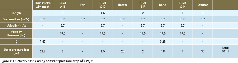
Figure 2: Ductwork sizing using constant pressure drop of 1 Pa/m.
The data used to determine the pressures throughout the duct system are shown in Figure 2. Clearly, the pressure drop in the straight lengths of ductwork is just a small part of the total pressure drop in the system. The pressures in the system may be plotted as in Figure 4. The pressure at the start and at the end of the ‘system’ (in the outdoor air and in the room) are shown as being the same, although frequently the pressure may be increased or reduced in the room by supplying slightly more or less air than is being extracted, as a means of controlling infiltration and exfiltration of air from adjacent spaces or outdoors.
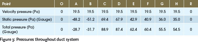
Figure 3: Pressures throughout duct system.
From the data shown in Figure 3 and Figure 4, the Fan Total Pressure may be obtained. This is the difference in the total pressure across the fan, and in this case is 88.9 – (-31.7) = 120.6Pa. This compares with the sum of the static pressure drops of 101.1Pa – the difference being a velocity pressure.
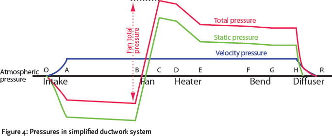
Figure 4: Pressures in simplified ductwork system.
For ducted air systems, the requirement is to select a fan that meets the required total flowrate and fan total pressure, so in this case a fan would be needed to provide a volume flow, qv, 0.7m3/s against a total pressure, pt, of 120.6 Pa. Assuming that a fan could be perfectly matched to this, then the electrical power, Pef , that would be needed to provide the required airflow would be:
Pef = (pt · qv)/η0 , where η0 is the overall efficiency of the fan and the motor assembly.
So if, say, the combined fan and motor efficiency is 65% then, in this case, the electrical input would be (0.6m3/s x 120.6Pa)/0.65 = 111 watts and, if the duration of operation is known, this can be simply changed to the energy consumption per time period. So, for example, if the system was to operate for eight hours per day, five days per week, 52 weeks per year, the annual electrical energy consumed would be: 111 watts x 3,600 seconds x 8 hours x 5 days x 52 weeks = 831 MegaJoules or, alternatively, (111 watts/1000) x 8 hours x 5 days x 52 weeks = 231 kWh.
This can be readily related to energy cost – assuming electricity is a nominal 0.15 pounds per kWh, this particular system would consume 231 x 0.15 = £34.65 per year. Similarly, the carbon impact of operation, based on Carbon Trustv figures, may be calculated as 231kWh x 0.54 kg CO2/kWh = 125 kg CO2 per annum.
The Building Regulationsvi relates the effectiveness of ventilation systems to ‘Specific Fan Power’ (SFP). In terms of the regulations, this is defined as the sum of the power used in both the supply and extract ventilation systems (and their associated control systems) divided by the ventilation flowrate in litres/second. However, SFP is frequently applied to single system (as opposed to the sum of the supply and extract), so in this case the SFP would be 111/600 = 0.185 J/l. (As a comparison, the Non-Domestic Building Services Compliance Guidevi that supports the England and Wales Building regulations would allow a maximum value of 0.6 J/l for such a system – but note that this example contains no filters, extract system or control power!)
Even this apparently simple system could usefully have changes made that would reduce the system pressure drop and so reduce the operational energy use. So, for example:
- Depending on space availability, the ductwork could be made circular – this will have a lower pressure drop. The actual shape and size of the duct will be infl uenced by a number of factors (see HVCA DW144vii for detailed guidance);
- The mesh covering the plain intake has a ζ factor related to its free area. This value can vary signifi cantly as the free area is changed. New designs of mesh on the market combine a large free area while maintaining good resistance to rain ingress;
- When selecting components for conditioning air (in this case, just a heater) the focus may be predominantly on the thermal performance of the equipment. However, the pressure drop in the components will affect the performance of the system at all times (whether the component is active or not) and should form part of the selection criteria;
- The pressure drop in any sections which change shape or direction (such as the bend in this system) can be signifi cantly reduced by adding splitters or turning vanes to keep the air fl owing smoothly – for example, the pressure drop in a rectangular bend can be readily reduced by more than 50% using turning vanes; and
- The design and quality of the fi nal air terminal device (such as the diffuser in this system) will vary between manufacturers. This may not make a large difference to the overall pressure drop but will contribute to continuous savings. And, for items not in the example system:
- Filters should be selected to meet the requirements of the application. Overspecified filter effectiveness is very likely to increase the filter’s pressure drop. The use of electrostatic filters will make significant reductions to pressure drops;
- Where sound attenuation is included, the application of longer silencers (or indeed electronic active noise attenuation) will result in lower pressure drops;
- Heat recovery systems can impose large pressure drops on the systems, and this should be carefully considered when comparing options. There may be a benefi t in applying bypass systems for periods when the heat recovery is not in use; and
- Aside from individual elements, the interactions between fans and downstream bends, transitions and components (such a heating and cooling coils) can increase the effective pressure drop, due to high velocity air jets impacting on duct walls and coils. In this small system, every saving of 10Pa will reduce annual running costs by about £3.26 and will reduce carbon emissions by around 9kg CO2 per year. Of course, in larger systems, such changes will have magnifi ed benefi ts.
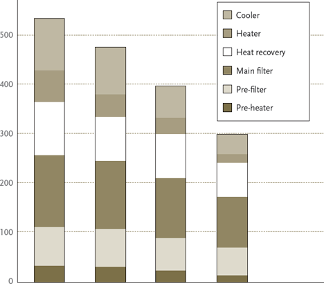
Figure 5: Reducing air handling pressure drop through careful selection.
Simply using lower pressure drop components and designs can provide remarkable benefi ts. The CIBSE publication Improve life cycle performance of mechanical ventilation systems – CIBSE TM30: 2003viii covers this area in greater detail, and shows that an offi ce using good practices in design and operation can practically halve the fan and pump energy use compared to a traditional (2003) design. For example Figure 5, taken from TM30, shows how the pressure drop of the air handling unit (AHU) may be reduced through thoughtful selection. This publication is highly recommended for anyone involved in ventilation system design, as it provides extensive comparative data and proposes a number of practical techniques to reduce the total life impact of air systems.
© Tim Dwyer 2011