A low carbon solution does not necessarily mean renewable technologies, as the requirement to provide power, heating and cooling for a building may exceed any realistically available local renewable resources; or there may be no appropriately oriented or available roof space. Combined heat and power (CHP) products have been applied and operated successfully as one of the solutions to reducing greenhouse gas emissions through displacing boiler fuel and grid-supplied electricity.
Over the last five years the uptake of mini-CHP units has increased in the UK, as the concept is scaled by manufacturers to products with electrical outputs of less than 10kWe (peak kW electrical output). This has broadened the range of residential and commercial projects that could benefit from the potential economic and environmental benefits offered by CHP.
This CPD module outlines the application of mini-CHP products, which we define as those with an electrical output of between 5kWe and 30kWe – representing the integrated modularised units that have come to the marketplace within the last five years. The traditional definition of mini-CHP goes up to several hundred kWe.
Combined heat and power technology
CHP can be an efficient way of producing usable heat and generating electricity simultaneously at the point of use from a single fuel. By generating heat and electricity from a single source, CHP can deliver overall fuel efficiencies well in excess of 75%. When compared with electricity generated from a centralised power station, and the use of heat only boilers, CHP can reduce primary energy needs by up to 30%. Depending on relative fuel prices this can reduce energy costs as well as reduce harmful greenhouse gas emissions such as carbon dioxide (CO2).
CHP can offer energy cost savings by reducing the amount of electricity imported from the local supply company, and by displacing fuel used by other heating and hot water-generating appliances on the site. For every unit of electricity generated by the CHP plant, around two units of potentially usable heat are produced through the use of internal heat exchangers, or external heat recovery equipment. This heat can be used to help satisfy space-heating needs, to support the production of domestic hot water, or for process needs.
At the heart of mini-CHP units (such as that shown in Figure 1) is likely to be a gas-fuelled reciprocating engine; or, for very small units, a Stirling engine. (See http://chp.defra.gov.uk/cms/gas-engines for an excellent overview of gas engines.)
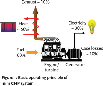
Fig. 1: Basic operating principle of mini-CHP system
Considerations for CHP applications
The primary consideration should be whether the application requires the simultaneous need for electricity and heat over extended operating periods, typically between 5,000 and 6,000 hours a year. The longer the operating hours, the greater the economic and environmental benefit delivered to the end user. For larger CHP installations, typical applications would naturally include sizeable consumers of hot water and power such as hospitals, universities, large chemical plants and paper mills. However, social housing developments and smaller properties such as hotels, leisure centres, nursing homes, and sheltered accommodation can all provide suitable applications for mini-CHP.

Fig. 2: 5.5 kWe mini-CHP Unit installed in plant room of sheltered housing scheme
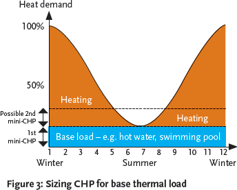
Fig. 3: Sizing CHP for base thermal load
The mini-CHP unit would normally be selected to match the base heating load of the site (as shown in Figure 3) to maximise the running hours. The success of all forms of CHP depend on the integration with the building’s heating system – particularly with engine-based technologies. Matching the CHP unit to the base thermal load must be the priority (that is, the system should be sized on a heat-led basis and not primarily on the electrical load). The CHP unit must be installed as the lead heating appliance, with existing or new boiler plant providing additional capacity to satisfy peak demand.
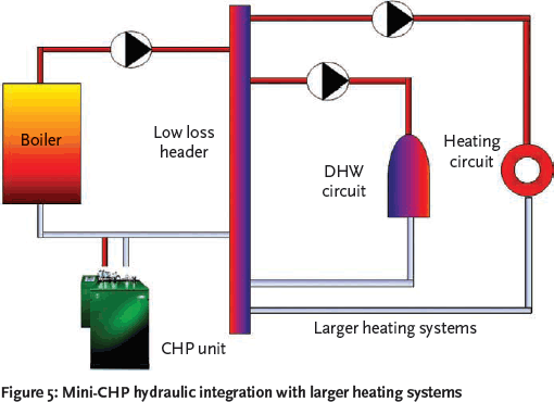
Fig. 5: Mini-CHP hydraulic integration with larger heating systems
Electrical integration
From an electricity generating perspective, the CHP unit should be selected to meet the site’s base load. This avoids or minimises the ‘spilling’ or exporting of electricity to the grid network, which at present on many sites would not offer a financially viable proposition. The key to maximising the economic benefit of the CHP scheme is to utilise all the electricity generated on site.
When operating in parallel with the local supply network, any electricity required above the output of the CHP unit would be imported from the grid network. For mini- CHP units that generate less than 16A per phase, connection and parallel operation with the electricity supply infrastructure should be carried out in accordance with Engineering Recommendation G.83/11, which is more ‘fit-and-inform’, rather than a formal connection agreement with the local Distribution Network Operator (DNO). For those CHP products generating more than 16A, a formal connection agreement between the DNO and the end user is required under the requirements of Engineering Recommendation G.59/12.
Depending on the electrical output and the current produced, most mini-CHP units will generate 3-phase electricity. For example, a commercially available unit has an electrical output of 5.5kWe, at 415V, 3-phase, 50Hz. This equates to approximately 9A per phase, and as such is below the threshold of G.83/1. This unit generates electricity equally across the 3-phases. It is therefore important to ensure that the electrical load that is to be supported by the mini-CHP unit is also relatively well balanced across the three phases. Otherwise, in the event of an under-loaded phase (with the load say less than 9A in the case of this unit), electricity will be erratically ‘spilled’ on the grid with loss of benefit to the end user. This is true of both new-build and refurbishment markets, but potentially is more of an issue with the latter.
If there is a 3-phase supply and distribution board in the plant room in which the CHP unit is installed, then electrical integration can be made locally rather than connecting at the main electrical incoming supply point, which may be some distance from the plant room.
Hydraulic integration
The installation of a mini-CHP unit should be no more complex than a conventional heating boiler. The plant room should be ventilated, taking into consideration the combined outputs of the mini-CHP unit and all other heating appliances present.
To maximise the annual operating hours, the CHP unit should be hydraulically integrated and controlled as the lead heating appliance. Care must be taken when considering the point of integration of the CHP unit flow and return connections.
If the water flow through the CHP unit is relatively low compared to the overall water volume in the system, then the CHP unit can be connected to pre-heat the return circuit water prior to entry into the main boiler plant. This results in the primary heating appliances not firing and their consuming less fuel to lift the water-flow temperature to the desired design set-point.
If the water flow through the CHP unit is relatively high compared to the system volume, then if connected as a pre-heat to the heating plant, there is a strong likelihood that the connection of the CHP will have an adverse effect on boiler efficiency, particularly if they are of the condensing type. Here reducing carbon emissions through the use of CHP would be negating carbon savings elsewhere in the heating system.

Fig. 4: Electrical integration of mini-CHP units
In both Figure 5 and Figure 6 the CHP unit has ‘access’ to both the heating and hot water loads via the low loss header. The ability of the CHP unit to serve both the heating and hot water loads is necessary to maximise the annual operating hours.
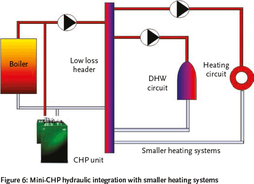
Fig. 6: Mini-CHP hydraulic integration with smaller heating systems
Depending on the base thermal load of the building, it may be prudent to install a buffer tank between the CHP unit(s) and the heating/ hot water circuits. This is to prevent frequent cycling of the CHP unit during periods of low thermal load, which could lead to premature engine failure.
For larger buildings, multiple mini-CHP units can be installed, as in Figure 7, on the premise that there are sufficient thermal and electrical base loads to support the combined outputs. The installation of multiple units versus a single larger CHP product is supported by an increase in operational flexibility, provides redundancy and improves load matching.
Environmental and economic case for CHP
The environmental case for CHP is based around the displacement of primary heating appliance fuel and grid supplied electricity. The CO2 reductions offered by CHP are a function of the emission factors for natural gas or LPG, and grid-supplied electricity depending on the generation mix being operated in the UK.
These are3:
| Grid-supplied electricity – | 0.529 kgCO2/kWh (displaced electricity) |
| Natural gas – | 0.198 kgCO2/kWh |
Hence, a 5.5kWe output commercially available mini-CHP unit would save around 8,700 kg CO2 per a year. This is on the basis of annual operational hours for the unit of around 5,600 (or 17 hours a day, 365 days a year, with a 90% availability), and displacing heat from the main boiler plant with an efficiency of around 80%.
The economic case for CHP is driven by what is often referred to as the ‘spark gap’. This is the ratio of the tariff for the imported grid-supplied electricity being displaced by the CHP unit and the cost of the fuel input. When considering CHP, the term ‘tri-generation’ or ‘CCHP’ is used to include cooling (using absorption refrigeration) as a means of extending the benefit of the heat produced by a CHP unit. However, this would not normally be economic for small or mini-CHP systems.
A standardised method to compare the effectiveness of CHP systems is to determine the quality index (QI) and power efficiency as defined by the DECC CHPQA programme4. This provides the principal evidence required for determining eligibility of CHP Schemes for Climate Change Levy (CCL) exemption and Enhanced Capital Allowances (which provide businesses with 100% first-year tax relief on qualifying capital expenditure).
For gas powered mini-CHP, the quality index can be determined from
The constants 249 and 115 are related to the alternative electricity supply and alternative heat supply options that are being displaced by the CHP unit – and vary for different applications of CHP4. Total Power Output is the total annual power generation from a CHP scheme as measured at the generator terminals. Qualifying heat output is the amount of useful heat supplied annually from a scheme that can be directly shown to displace heat that would otherwise be supplied from other sources. The total fuel input is the annual fuel input to a CHP Scheme.
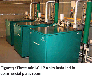
Fig. 7: Three mini-CHP units installed in commercial plant room
A QI of 100 is the basic benchmark, and QI should be at least 105 with a minimum power efficiency of 20% in order to help qualify for government incentives, enhanced capital allowances and CCL exemption. The fuel consumption to the CHP unit will require a dedicated gas meter, and the heat and electricity output will need metering.
Conclusion
In a time when there seems to be huge industry focus on renewable technologies, whether such solutions are generating electricity or heat, CHP can play its part as a low carbon solution in achieving the increasingly stringent emission reduction targets, whatever the driver.
By the nature of its lower electrical and thermal outputs, mini-CHP now presents the benefits offered by CHP to a much wider range of buildings.
© Yan Evans and Tim Dwyer
References
- Engineering Recommendation G.83/1-1, Recommendations for the connection of small-scale embedded generators (up to 16A per phase) in parallel with public low-voltage distribution networks. Ofgem, 2008
- Engineering Recommendation G.59/1, Recommendations for the Connection of Embedded Generating Plant to the Regional Electricity Companies’ Distribution Systems. Ofgem, 1995
- The Government’s Standard Assessment Procedure for Energy Rating of Dwellings. Building Research Establishment, 2010
- CHP QA – Quality Assurance for Combined Heat and Power. www.chpqa.com