
![]()
This CPD will consider some of the room factors that may be neglected when assessing a prospective boiler installation for a commercial building, including the impact on installed capacity resulting from the intermittent use of a building.
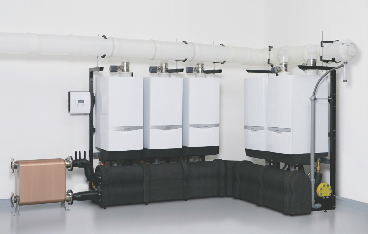
Figure 1: Example modular boiler system with fully modulating gas boilers that consistently operate at high efficiency with local control (as shown here) and/or by integration with the building energy system. This ensures return water temperatures are cool enough to allow boilers to operate in condensing mode (Source: Vaillant)
The sizing of commercial building heating is becoming more exacting as modern standards and regulations reduce heat losses from buildings. Outdated ‘rules of thumb’ can promote improperly sized systems and – even when calculations are properly undertaken – inappropriately applied past experience can encourage unreasonable ‘safety factors’. This can produce design loads that, at best, will mean that the capital costs will increase, as the boilers and distribution systems can become oversized, while, at worst, the operational effectiveness of the resulting system may be reduced – so increasing environmental emissions and operating costs for the whole installed lifetime of the system.
The application of modular boiler systems (such as those shown in Figure 1) will allow high-efficiency, part-load operation, since separately pumped boilers are brought online only as the load demands. The calculated total peak load will determine the capital cost of boiler modules, distribution networks, emitters and space requirements.
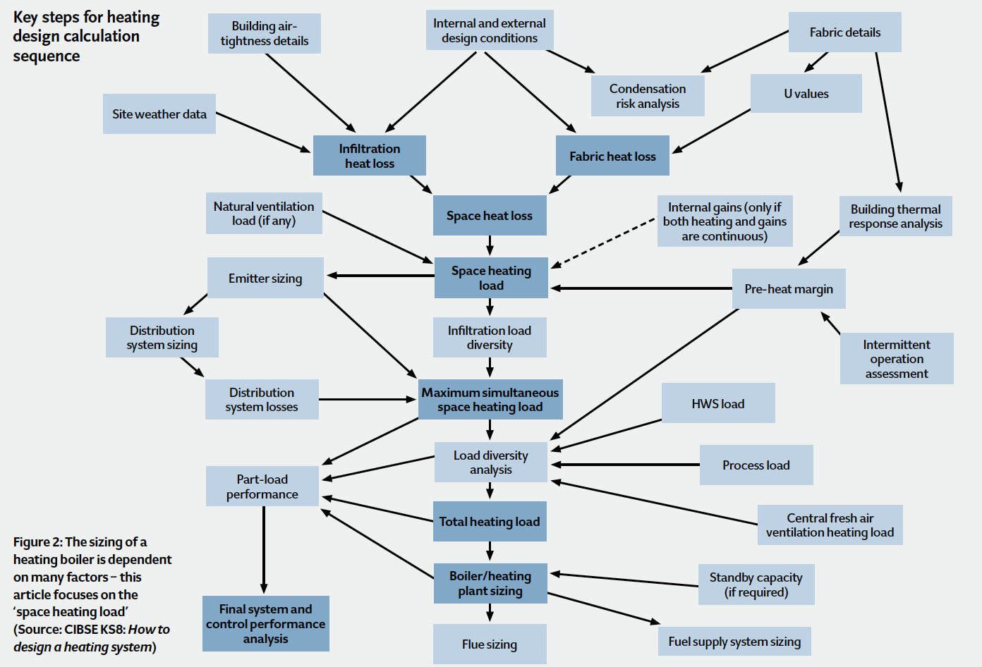
The route to an appropriate boiler size might look complex (Figure 2). However, it is the very interdependencies of a holistic approach – considering the whole set of building ‘systems’ – that will provide an installed boiler capacity based on the real requirements of a building. For many designers, heating loads are generated at the press of a button, or from a few entries in a spreadsheet; however, it is worth reviewing how these loads would compare with those produced considering the factors discussed in the 2015 revision of CIBSE Guide A, as a check on these everyday methods. This article will focus on the assessment of the individual space heating load for typical commercial buildings with typical ‘office hours’ occupation.
The relatively simple CIBSE steady-state calculation is appropriate for normal commercial applications, to evaluate room heat losses that will typically combine – together with potable hot water loads – to determine the boiler size. As identified and discussed in the recently updated Section A5 of the CIBSE Guide1, reliable input will be required for the specific project, including:
- Thermal properties of materials – specifically U value, admittance (see CIBSE Guide A3)
- Internal design conditions – principally dry resultant temperature and the period of occupation (see CIBSE Guide A1)
- Outside air requirement to deliver required indoor air quality – the relative significance of heating the ventilation air increases as the heat flow through the fabric is reduced (see CIBSE Guide A1 and A4)
- Internal gains – intermittent gains may normally be ignored for determining peak loads; however, it is important to determine these, as they will be required for subsequent energy modelling (see CIBSE Guide A6)
- External design conditions – for heating loads this is normally dry bulb temperature, although extremes of other climatic parameters, such as wind and rain, might affect fabric thermal properties (see CIBSE Guide A2).
The size of a heat emitter will be determined from the steady state heat loss from the space, based on the concepts developed for the ‘admittance method’. This gives the room total heat loss equation as:
Room heat loss (W) = [F1cu x general thermal transmission coefficient + F2cu x ventilation heat transmission coefficient] (θc – θao)
θc is the operative temperature at the centre of room (°C) and θao is the outside air temperature (°C). F1cu and F2cu enable the use of (θc – θao) in the above equation for both the environmental heat transfer for the surfaces (that includes radiant and convective modes of heat transfer), as well as pure convective heat transfer from the ventilation components. As derived in appendix A2 of CIBSE Guide A5
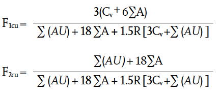
∑(AU) is the sum of the product of each surface where there is heat flow (for example, to outside or significantly cooler rooms), multiplied by its thermal transmittance (W·K-1); ∑A is the sum of all the internal surface areas in the room (m2); Cv is the ‘ventilation heat transmission coefficient’ (W·K-1) and is obtained from
Cv = 0.33N·V where N is the ventilation and/or infiltration rate of directly incoming outdoor air (h-1) and V is the room volume (m3). R is the heat emitter radiant component, ranging from fully radiant heaters R=1 to warm air heating where R=0.
The value of N will be dominated (ideally) by the designed ‘fresh’ air required to maintain appropriate indoor air quality. Since the leakage of air into a building will tend to alter with wind direction, CIBSE Guide A5 notes that, when considering a boiler to heat a number of rooms in a building, ‘the total net infiltration of outdoor air is about half the sum of the rates for the separate rooms. This is because, at any one time, infiltration of outdoor air takes place only on the windward part of the building, the flow in the remainder being outwards’, and refers to CIBSE Guide A4 for more detail.
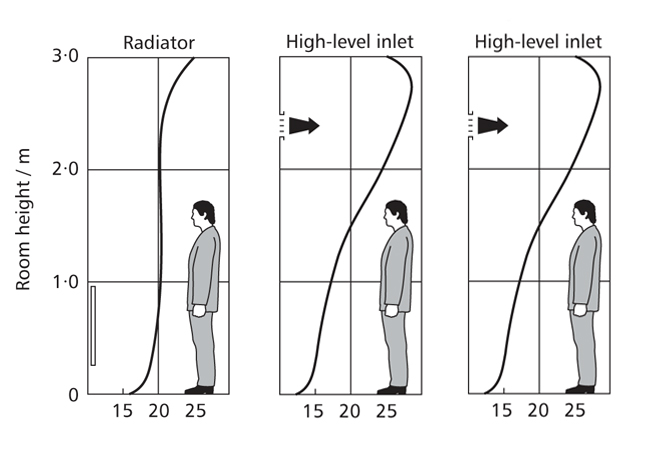
Figure 3: Influence of room heat emitter on temperature in space (Source: selection from CIBSE Guide A Fig 5.19)
As insulation standards have significantly improved since the original development of this simplified application of the admittance method, the effect of thermal bridging has become more significant when considering the overall performance of a room. Hence the ‘general thermal transmission coefficient’, Hx, should take account of the normal heat flow through the surfaces, as well as additional heat flow through thermal bridges. Thermal bridging is likely to be more significant in smaller rooms and spaces, and those where there are generally high levels of insulation. So, the general thermal transmission coefficient is given by (∑(AU) + HΨ) where HΨ is the sum of thermal transfer coefficients for linear and point thermal bridges (see CIBSE Guide Section A3.3 for more details of thermal bridging).
There may be a case, where the value of HΨ is significant (compared with ∑(AU)), that the values of F1cu and F2cu should be reassessed, with ∑(AU) being replaced by (∑(AU) + HΨ).
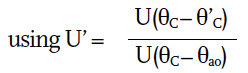
Individual U values (for use in the ∑(AU) calculation), may be adjusted for those surfaces that are adjacent to other, cooler, indoor spaces (not outside walls) at a temperature of θ’C’
There is a simple worked example of a steady state heat loss in appendix A6.1 of section A5 – but note that a typographic error carries an incorrect value of ∑(AU) forward from Table 5.A6.3 as provided in the example.
The type of heating system will not only affect the heating requirement because of its mode of heat transfer, but also by its location. With a ‘radiator’-type system, with a surface temperature θH and rear area of AH, there will be an additional heat loss from the back of the radiator through the wall (Uw) on which it is mounted. This additional loss can be estimated from (θH – θc)Uw·AH. For traditional 80°C/60°C system, that would mean, practically, around 12 watts per square metre of rear radiator surface. Modern systems are likely to operate with lower mean water temperatures (for example, 45°C, so as to allow condensing of flue gases in the boiler), and hence the additional loss from the rear of the radiator would be nearer 6 W·m-2.
For the simple heat loss calculation, a uniform temperature is assumed across the height of the space. Figure 3 represents the temperature profile across the height of a room – such as an office – for two common types of heating systems. It is clear that there is a significant variation in temperature for the high-level heated air inlet system. This will affect the heat loss, since the average room temperature will be higher than that with, for example, the radiator system. The actual temperature gradient will be dependent on the height of the space, and to accurately predict the effect on the heat loss would require some detailed analysis. CIBSE Guide A provides some guidance (in Table A5.11) that, broadly summarised, would mean, for an office of 3m height, the additional heating required for a heated air system (either low and high level supply) would be up to 5% higher than for a system using radiators. As the space increases in height, the additional percentage heat loss will also rise.
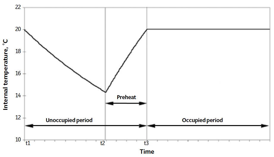
Figure 4: Internal temperature variations in an intermittently heated building (Source CIBSE TM41)
The other significant effect addressed in the CIBSE Guide that is relevant to sizing of heating requirement for a commercial space, is intermittent operation, where the boiler and heating distribution is switched off when occupants leave, and turned on before the next period of occupancy. The required preheat period (as shown in Figure 4, time t2 to t3) will depend on the thermal characteristics of the building (and its systems), the occupation time and the external conditions. In many cases, the unoccupied requirement may simply be that the internal temperature should not fall below 10°C (as a reasonable precaution to ensure that the air does reach its dew point, thereby preventing condensation).
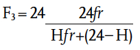
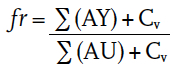
A longer preheat period will increase the overall heat loss but will require a smaller heating system, and vice versa, so a balance must be struck. This proper assessment is no simple matter, since the variables are dependent not just on the building thermal performance, but also on the heating system costs and part load performance – this is a case where software modelling can usefully be exploited (see CIBSE TM412 for an excellent discussion of the underlying issues). Since the detailed methods in TM41 tend to predict excessively long preheat times, CIBSE Guide A5 suggests that a very simple multiplying factor, F3, may be used to adjust the steady state heat loss (where preheat times are greater than one to two hours) to allow for a building that is occupied H hours a day where
As can be seen from the brief discussion in this article, there are clearly opportunities where applying dynamic thermal simulation tools will be ideal. However, in many cases
this will not be feasible or available. It is, therefore, important when using the
simpler methods of heating load assessment that the wider considerations should be understood and properly considered, to
ensure that appropriate boiler selections are made to meet the ambitions of the predicted building performance to satisfy the demands
of the user.
© Tim Dwyer, 2016.
References:
- CIBSE Guide A5 Thermal design, plant sizing and energy conservation, CIBSE 2015.
- CIBSE TM41 Degree-days: theory and application, CIBSE 2006.