

The application of variable refrigerant flow (VRF), ‘multi-split’ technology is now commonplace as a means of providing temperature control and limiting maximum humidity for commercial buildings in Europe and Asia. Although still in its infancy in the USA, it is soon likely to see a step change in application, following a positive assessment by the General Services Administration (GSA)1 of VRF technology in US government newbuild and refurbishment projects. There are a handful of principal manufacturers in this buoyant and competitive marketplace, and each one is striving to improve their product to provide an increasingly effective solution. This CPD will consider some of the key areas that manufacturers are concentrating on to improve VRF performance and further reinforce the global reach of the technology.
The current credentials of VRF
In recent years, there has been a shift in what many users consider as ‘air conditioning’. The conventional view is that ‘air conditioning’ is a system that controls the internal environmental conditions through moving conditioned air into the space. However, contemporary users are increasingly considering ‘air conditioning’ as systems that comprise an internal fan coil unit (often as part of a larger network of internal coils) connected, via refrigerant pipes, to an outdoor coil and a refrigerant compressor – known as a ‘multi-split’. Practically, the HVAC engineer understands that these multi-split units provide what has been traditionally termed ‘comfort cooling and heating’, where the space temperature is controlled by re-circulating room air through the room coil to provide sensible cooling. Dehumidification (latent cooling) can also be provided through the room unit coil temperature being designed to operate at temperatures below the dew point of the incoming room air where there is appropriate condensate drainage. By varying the refrigerant flowrate to the room units using electronic expansion valves (EEV) and variable speed compressors, in conjunction with variable speed fans passing air across the heat exchangers, the internal re-circulated air temperature may be closely controlled to meet the demands of the room.
A separate ducted air system (increasingly known as a ‘dedicated outdoor air system’, or ‘DOAS’) typically provides filtered and partially conditioned outdoor air and, optionally, humidification. Since the VRF system is operating to meet the majority of the heating and cooling load, the air system is sized to provide only the outdoor (‘fresh’) air requirement, so is often much smaller than a traditional ducted system that meets the full load. As discussed in the April 2013 CIBSE Journal CPD article,2 the advances in control and refrigerant piping techniques have boosted the potential operating efficiencies of VRF systems by effectively shifting heat from one room unit to another, so allowing concurrent heating and cooling to benefit from heat that would otherwise be rejected through the outdoor unit.
This, of course, is in addition to the unit acting as a heat pump, using outdoor air as a heat source. Recent research1,3 has shown that the resulting properly applied VRF systems may not only consume less energy than traditional air conditioning systems – such as variable air volume and fan-coil plus fresh air – but can also provide good environmental control. Case studies indicate that the higher initial cost would be paid back in a relatively short time – the US-based study suggested payback of 1.5 years, but this would be dependent on local absolute and relative fuel prices.
Climates such as that of the UK can provide better opportunities for heat recovery (as opposed to warmer climates typical in southern Europe), especially if there are building zones providing constant cooling requirements. The opportunity is enhanced if there are significant north and south exposures on the same building.1
Improving systems to lead the market
Although this technological application was invented in Japan more than 20 years ago, it has since become an international product. In the UK, the data collected as part of the EU Ecodesign research4 into air conditioning systems (with a cooling capacity of greater than 12 kW) indicated that in 2008 VRF already provided 18% of installed cooling (compared with 44% for more ‘traditional’ systems). This proportion is likely to have increased substantially in the last five years, but in that same period the demand for ‘value engineered’ products has also risen to meet ever more closely scrutinised budgets.
Manufacturers have evolved their product ranges to meet the demand for lowest life-cycle costs (LLCC) by examining the thermodynamic operation of their systems and determining areas where newer technologies – or applications – can enhance overall performance. Examples include developments in motors, coils and control techniques.
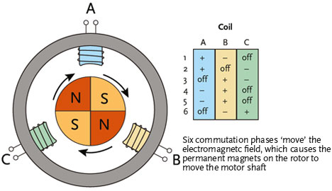
Figure 1: A simplified BLDC motor indicating the field rotation5
Motors
Alternating current (AC) induction motors have been used traditionally to drive the fans and compressors in split air conditioning applications. Brushless direct current (DC) motors (BLDC) – otherwise known as electronically commutated (ECM) motors – started out in small domestic motor applications some 25 years ago and, due to their controllability and efficiency, have now usurped the AC motor in commercial VRF units.
These have pairs of windings arranged around the stator (the non-moving section of a motor) that are charged in sequence, so magnetizing specific sections of the circular stator that face a set of permanent magnets mounted on the perimeter of a circular rotor. The rotor can be arranged around the outside of the stator and, for example, used as the hub for an axial flow fan or, for applications such as scroll compressors, the rotor will be inside the circular rotor and act as the shaft for the scroll (as shown in Figure 1). The key advantage is that the speed may be closely controlled across a wide range by a pulsing field that moves the around the stator. The controller (which is typically mounted in the end ‘cap’ of the motor) varies the rotating pulse speed, synchronising the pulses with the exact position of the rotor, delivering accurate and efficient control at a wide range of speeds (and loads). Although the motor itself is DC, the supply would normally be AC and the power will be rectified (in the end cap control circuit) – a low voltage line will provide the signal from the main controller in the VRF system to finely adjust the motor speed. The efficiencies at full load are similar to that of a good quality AC induction motor. However, unlike AC motors, relatively high efficiencies are maintained throughout the operating range. By virtue of the close control of field rotation, a BLDC motor can be ‘soft’ started and stopped, reducing the wear and noise in the motor and surges in the system.
As efficiency is uniformly high, less heat is produced in the motor, so less uncontrolled heat is passed to the surroundings (the air or refrigerant) and the motor runs cooler. BLDC motors create far less electrical and audible noise, but due to the switching action of the onboard controller, they will increase the harmonic distortion in the electrical supply – this can be readily ameliorated in the supply system.
Brushed DC motors are also able to offer variable speed control, but with the drawback of ‘brushes’ to carry the power to the mechanical commutator. Without carbon brushes that wear out, brushless DC motors have design lives equal to – or longer than – AC motors.
BLDC motors are applied in VRF units both to power both fans and compressors, providing a wide and efficient working range.
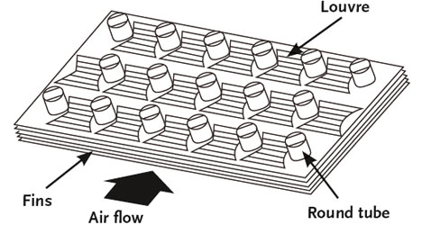
Figure 2: Example louvred fin coil6
Coil fin geometry
The design of coils in any HVAC equipment determines the performance of the fundamental principle of the plant: to exchange heat from one medium to another without the two media mixing. In a VRF system, the internal and external coils have two-phase heat exchange inside the tubes of the coil (refrigerant liquid and vapour) and potentially two-phase heat transfer on the outside (air and condensation). An example of a coil made of round tubes (carrying the refrigerant) with air passing across the louvred fin coil is shown in Figure 2. The characterising performance of the air side of the coil is provided by the ‘Colburn J-factor’ – a dimensionless heat-transfer relationship that is used to determine the potential heat flow from the surfaces of the fin coil to the air; and the ‘Fanning friction factor’ that establishes the air pressure drop (and so, ultimately, fan power) for the air passing through the coil.
Manufacturers undertake analysis (which would typically use computational fluid dynamics CFD) on the numbers of rows, the shape and sizes of tubes and the form of the fins required to establish optimum and cost-effective arrangements for heat transfer and pressure drop. This is a complex task for systems where the temperature, humidity and passing air velocity will vary independently. As reported by Wang,6 there appears to be a clear relationship between the velocity of the air and the most effective number of rows of coils (for heat transfer). However, the relationship is further complicated, as described by Wongwises,7 as the thickness of the fins and the number of rows will also affect the Colburn J-factor but be dependent on air velocity – very broadly, for coils with at least four rows, at lower air velocities thinner fins are preferable, whereas as the air flow rate increases the fins perform better when thicker. As fabrication methods evolve, the complex analysis used enables the design of such coils to progress so that, as in the example shown in Figure 3, what might be minor changes to the fin design visually can make significant improvements in performance.
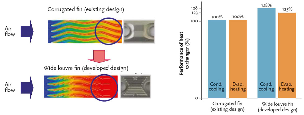
Figure 3: Example of manufacturer development coil fins to improve VRF system performance8
Similarly, engineering developments on the refrigerant side of the coil can enhance performance. For example, to make optimum use of the internal heat transfer surfaces, the refrigerant should be distributed evenly across all the individual coil loops. Figure 4 provides an illustration of a developed distributor assembly that, through the use of a buffer section, ensures an improved distribution across the multiple loops that make up the complete coil arrangement compared with an un-buffered plain pipe version that was typically used in previous systems.
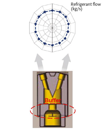
Figure 4: Ensuring evenly distributed refrigerant flow to coils8
Enhanced control techniques
The very existence of heat recovery VRF systems is a tribute to the imaginative digital control systems and closely engineered components that allow concurrent heating, cooling and optimised heat recovery across multiple room units, powered by a single external variable speed compressor unit.
But, as with all heat pump systems, at times of low external temperature, when the external coil is acting as an evaporator, the coil will accumulate ice that, if left, would prevent the evaporator functioning. All such systems require some ‘defrost’ arrangements (increasing the temperature of the evaporator to melt ice/snow) that will adversely affect the overall performance of the system, most notably below external temperatures of around 7°C. As the external temperature drops below 0°C, the air’s moisture content becomes very low so there is a reduced rate of ice accumulation. By applying novel control arrangements, the adverse effect of the defrost cycle can be reduced. The example in Figure 5 shows that by segmenting the coil into separate sections, the controller can determine a cycle that selectively defrosts just part of the coil at a time. This will ensure that the overall system will still be able to use the remaining parts of the coil as an active evaporator (and so continue to heat the building from the heat pump) and, through using such arrangements, the manufacturer has shown that the heat pump availability is improved by more than 6% at 0°C.
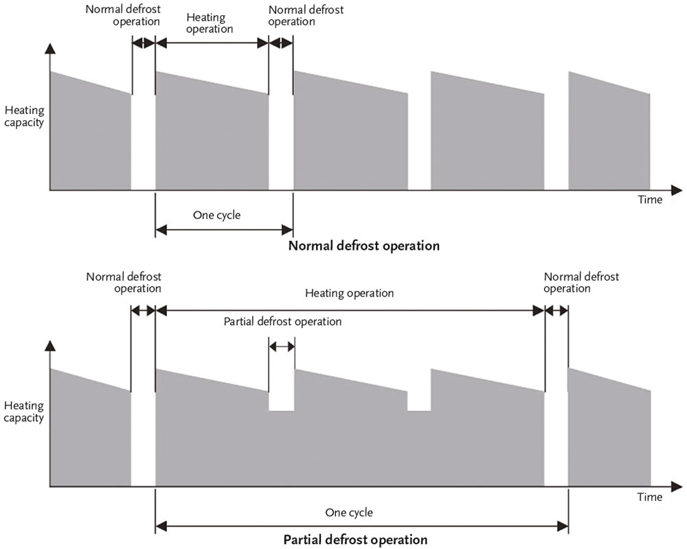
Figure 5: Example of VAV fume cupboard layout for a laboratory
The appropriate application of heat recovery VRF in buildings can reduce energy consumption, costs and the operational carbon footprint. The technology has matured so that it is supplanting traditional air based systems in many applications, and with continued developments such as those outlined in this article, it would appear to offer even greater opportunities in future.
© Tim Dwyer, 2013.
References
- Thornton, B and Wagner, A, Variable Refrigerant Flow Systems, Pacific Northwest National Laboratory/GSA, December 2012
- Dwyer, TC, Air source VRF systems for flexible room heating and cooling, heat recovery and hydronic heating, CIBSE Journal, April 2013
- Aynur, T, Variable refrigerant flow systems: A review, Energy and Buildings, 42 pp1106–1112, 2010
- Riviere, P, Energy-Using Product Group Analysis Lot 6: Airconditioning systems – Final report of Task 2 – Air-conditioning products, EU DG Enterprise, July 2012
- Source: http://dev.emcelettronica.com/you-use-bldcmotor-you-should-understand-how-it-works-brushless-dcmotors-roll, accessed October 2013
- Wang, CC et al, An experimental study of heat transfer and friction characteristics of typical louvre fin-and-tube heat exchangers, Energy and Resources Laboratories, Chung Yuan Christian University, Taiwan, Int J of Mass Transfer. Vol 41, Nos 65, pp 817-822, 1998
- Wongwises, S et al, Effect of fin thickness on air-side performance of herringbone wavy fin-and-tube heat exchangers, Heat Mass Transfer 41: 147–154, 2004.
- LG Multi V internal publication – accessed October 2013
- LG Multi V (R410a) Technical Data Sheet – accessed October 2013