The Tate wanted the environmental design of the Switch House extension to London’s Tate Modern gallery to be as cutting-edge as the art installations it showcases.
‘The client’s brief was for the building to be agenda-setting and to take a leading role in sustainability,’ says Mark Nutley, senior partner at Max Fordham, the project’s environmental engineers.
Max Fordham’s scheme does not disappoint. It uses ground water pumped from river gravel below the site, desiccant dehumidification and even waste heat from electrical transformers to create the ideal environmental conditions for the Tate’s priceless works of art, while ensuring millions of visitors are comfortable.
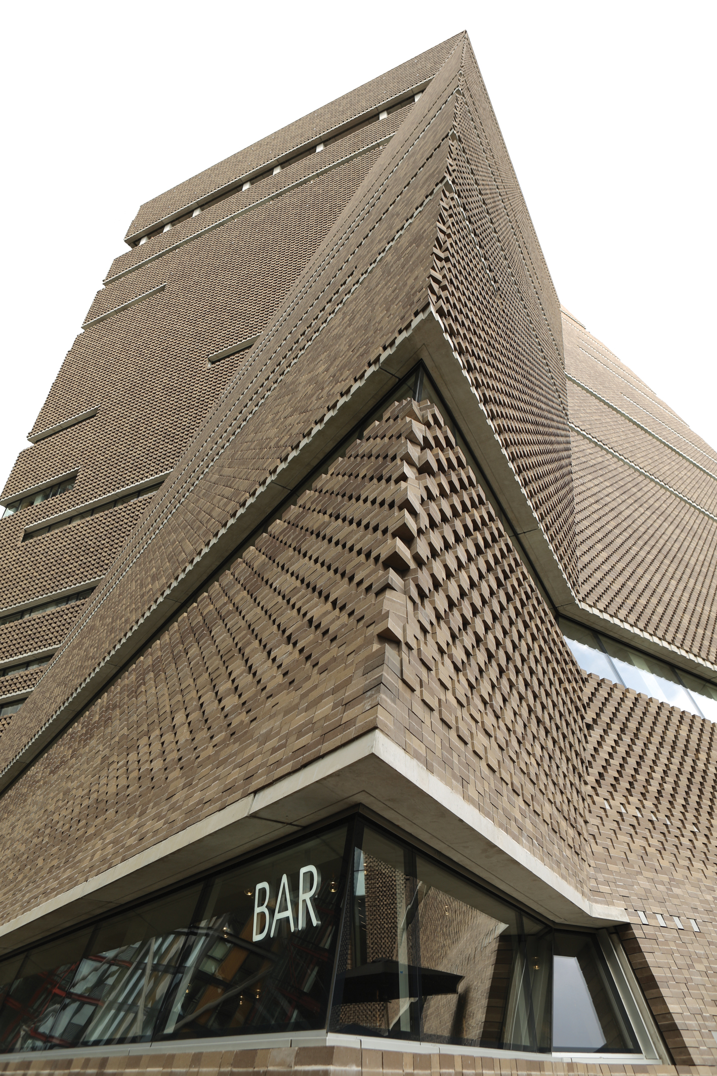
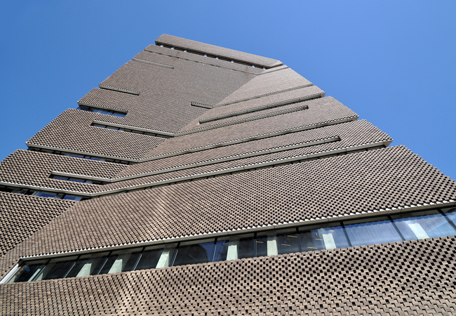
Max Fordham’s first involvement with the Thames-side gallery was in autumn 2007, after architect Herzog & de Meuron had radically changed the design for the extension from a jumbled collection of glazed boxes to a folded, perforated brick façade, wrapped around a 10-storey-high truncated pyramid.
Herzog & de Meuron was also the architect that transformed the 1950s power station into a contemporary art gallery for the millennium. At the time, It was designed to be a fully air-conditioned box.
With almost five million people passing through the Tate Modern each year, air conditioning and humidity control are essential in the galleries, to protect exhibits. The circulation areas, toilets and members’ areas are also all air conditioned.
But given concerns over climate change, air conditioning the entire building was no longer appropriate for the extension’s environmental strategy, says Nutley. ‘For Switch House, we adopted a different approach that is pioneering in a gallery environment,’ he adds.
Creating the right conditions
Max Fordham developed solutions specific to each type of space – be it a gallery, restaurant or circulation area – to ensure the most appropriate low-energy design. ‘The heating and cooling strategy was driven by an ambition to reduce energy consumption to as low a level as realistically feasible,’ says Nutley.
Because of their critical importance, the Tate was very prescriptive about the environmental conditions that had to be maintained in the galleries to protect the artwork and ensure that works continue to be loaned to the Tate from other galleries. As per the international loan standards for art, the temperature is maintained between 18°C and 25°C, and the relative humidity (RH) between 40% and 65%. ‘People won’t lend to a gallery unless appropriate conditions can be maintained,’ says Nutley, who adds that the Tate is happy to ‘vary conditions slightly’ to save energy as the seasons change.
In winter, for example, the extension’s galleries are maintained at the lower end of the temperature and humidity range, but still within loan standard criteria. This means that the galleries aim for a temperature of 19°C +/- 1°C and an RH of 50% +/- 5%. In summer, the limits are increased to 22°C +/- 2°C, with an RH of 55% +/- 5%. ‘The important thing is limiting the speed of variation – you want a maximum of 10% variation in RH and a 4°C change in temperature in any 24-hour period,’ says Nutley.
Illuminating art
Jeff Shaw, SLL president and associate director at Arup, explains the lighting strategy at the Switch House extension
A key challenge for the design of the internal lighting was to develop a scheme that integrated with – and accentuated – the architecture of the new spaces, while maintaining a feel consistent with the existing building.
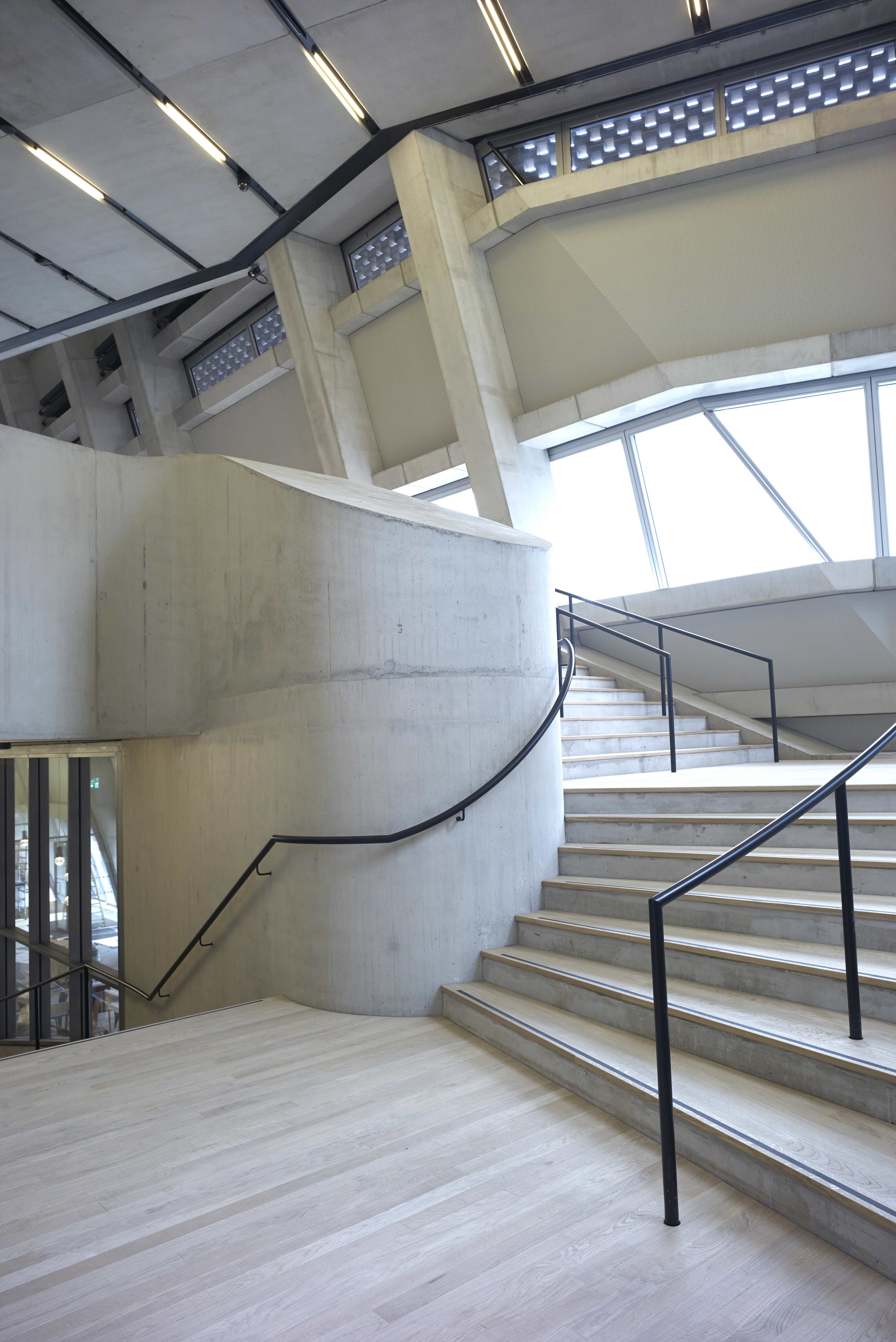
The scheme for public circulation comprises bare fluorescent lamps slotting between precast concrete panels, both to complement the form and finishes of spaces, and to help draw people through the vertical building towards the galleries and other public areas.
This approach is adapted to take into account the lighting requirements for the wide variety of social and educational spaces for patrons, enhancing the overall visitor experience. LED cast-glass decorative pendants add character and sparkle to the dining spaces without distracting from the spectacular views over London.
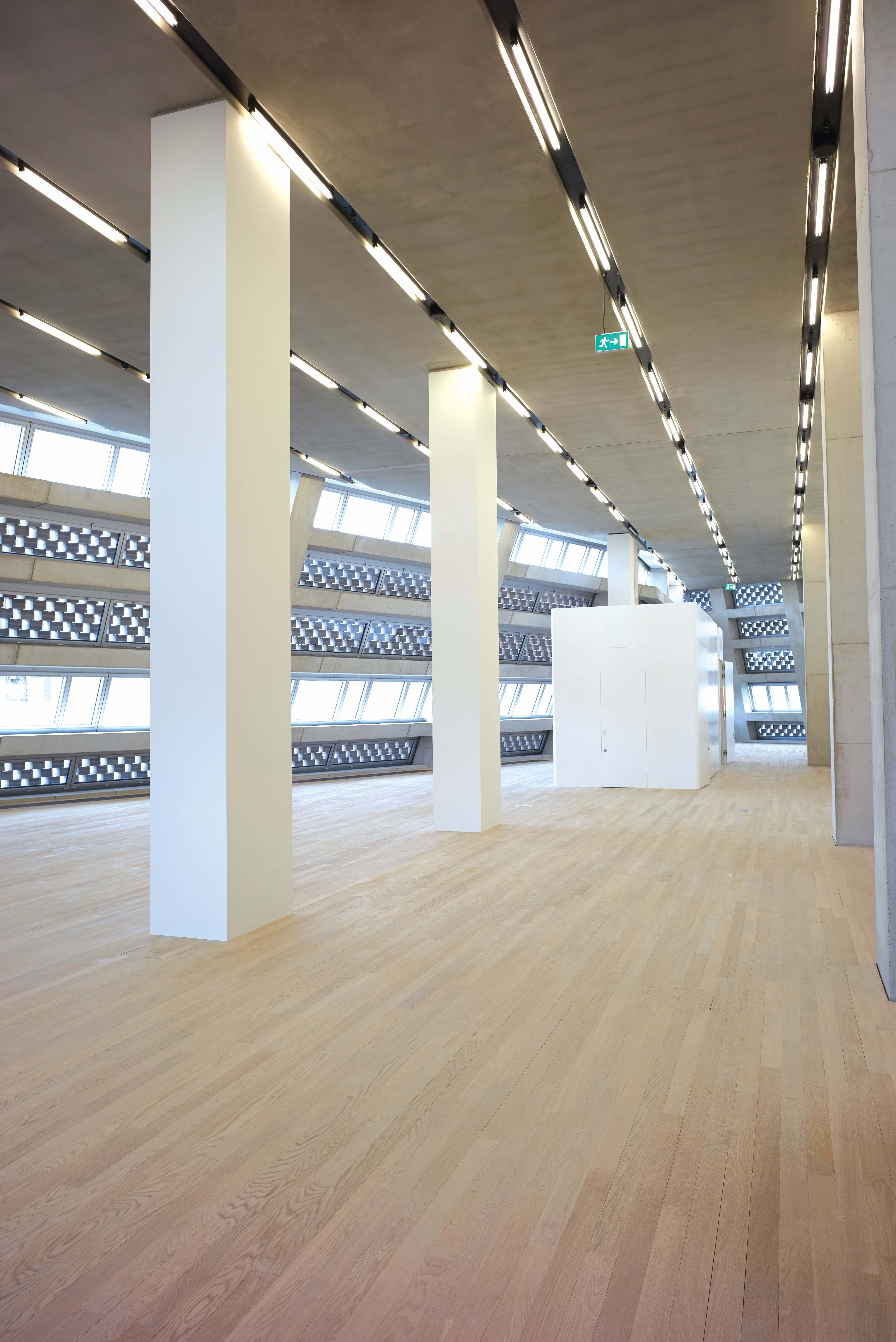
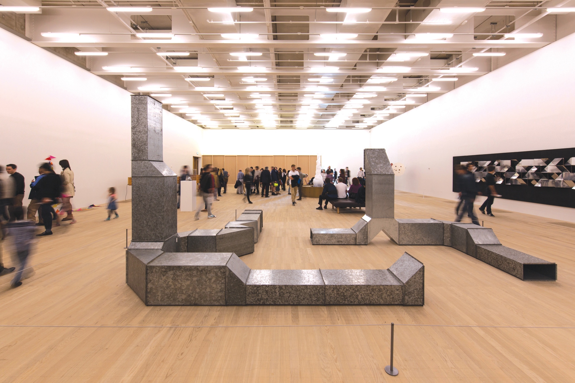
The Switch House includes a variety of new gallery spaces, giving it flexibility to display a wide range of artworks. Galleries on Level 3 are more intimate spaces with track and spotlights only. The larger galleries on Levels 2 and 4 are supplied with homogenous ambient light using high colour rendering fluorescent lighting, with exposed lamps on Level 2 and backlit ceilings on Level 4. Half of the Level 4 gallery space also has generous – but controlled – levels of daylight through a system of skylights above the ceiling, with the sunlight blocked by external shading and the daylight diffused to create a comfortable and appropriate daylit environment for viewing and for protecting the art on display.
The LED spotlights used in the galleries – barely distinguishable in quality and appearance from traditional halogen lighting – more than halved the gallery energy demand from that of traditional galleries.
A displacement ventilation system supplies conditioned air to the extension’s three gallery floors; conditioned air is supplied through floor grilles and extracted at high level. This is a similar strategy to the one used in the original Tate Modern building. The main difference is that air is ducted to the floor grilles in the extension, whereas conditioned air in the power station reaches the floor-mounted grilles through a pressurised, raised-floor void.
‘The problem with floor voids in galleries is that they can get dusty, so by ducting the air, it makes the system easier to clean,’ Nutley explains.
Ductwork supplying air to the floor grilles is run at high level in the gallery below – along with that gallery’s high-level extract ductwork – from where it punches up through the floor slabs to the grilles. In the larger, lower-level galleries, the supply and extract ductwork have been painted white and left exposed. ‘The ductwork in the ceiling can be seen, but it doesn’t detract from the artwork,’ says Nutley. On the upper floors – where the smaller galleries are situated – the extract ducts are hidden above a suspended ceiling.
Innovative cooling
Each gallery has a dedicated air handling unit (AHU). In an unusual low-energy solution, the engineer has pioneered the use of ground water trapped in a five-metre-deep bed of river gravel beneath the site as a source of cooling for the AHUs.
The gravel has been deposited over thousands of years by the meandering of the adjacent River Thames. It is saturated with water permeating into the ground from soft landscaping, leakage from the Thames and from sewers, and from several of London’s buried rivers. The water the gravel contains flows very slowly eastwards towards the sea. ‘In the past, schemes have used water from the chalk aquifer beneath London for ground-water cooling, but using the river gravel on this scale is pioneering,’ says Nutley.
Water is extracted from the gravel at a rate of up to 30 litres per second – at a ‘useful’ temperature of 14-15°C – via two boreholes situated close to the Tate’s western entrance. The gravel is between 5m and 12m beneath the surface, so pumping water up from them does not consume a significant amount of energy.
Once at the surface, the water passes through a heat exchanger to keep it separate from the sealed gallery systems. The borehole-cooled water is then passed through large coils fitted to the extension’s numerous AHUs. ‘Although it passes through a heat exchanger, we effectively use it to provide cooling directly to the AHUs,’ says Nutley.
The scheme also features three water-cooled chillers. These supply higher-grade chilled water to cool some of the basement spaces and other ancillary areas.
Heat rejected by the chillers is removed by the borehole water and returned to the gravel via three boreholes sunk into the landscaping to the north of the gallery. ‘Compared to using air-cooled chillers, it is a very efficient solution,’ says Nutley.
In winter, the borehole water is also passed through a heat pump. The heat generated is used to satisfy part of the building’s heat demand. Backup heat is obtained from spare capacity in the existing gallery’s boilers. ‘The boreholes provide all of our cooling and a fair bit of our heating as well,’ says Nutley.
Another pioneering approach is the design of the building’s systems to maximise the use of waste heat produced by UK Power Networks’ large arrangement of transformers that supplies the City of London with 11kVA of power.
The transformers’ Bankside location is a relic of the Tate Modern’s previous incarnation as a power station. They were originally housed in the entire Switch House, but were relocated to its east end, enabling the extension to be built. They are water-cooled, and relocating them gave the engineers the opportunity to use the rejected heat in the new extension.
Controlling humidity
Humidity control is critical in the galleries. The conventional approach to dehumidifying fresh air is to over-cool it so the water vapour condenses from the air, before reheating it to bring it back up to a comfortable supply temperature. This process uses a large amount of energy.
However, the significant quantity of low-grade cooling and heat available from the boreholes and the transformers enabled desiccant dehumidification to be applied to remove moisture from the extension’s fresh-air supply.
Desiccant material easily attracts and holds water vapour. A 4m-diameter desiccant wheel is used to dehumidify the fresh-air supply to the Switch House extension. The moisture absorbed by the wheel is then driven from the desiccant using the low-grade heat in the reactivation air stream, which recharges the desiccant. The dehumidified air is ducted to each of the dedicated gallery AHUs, where it mixes with the recirculated gallery air.
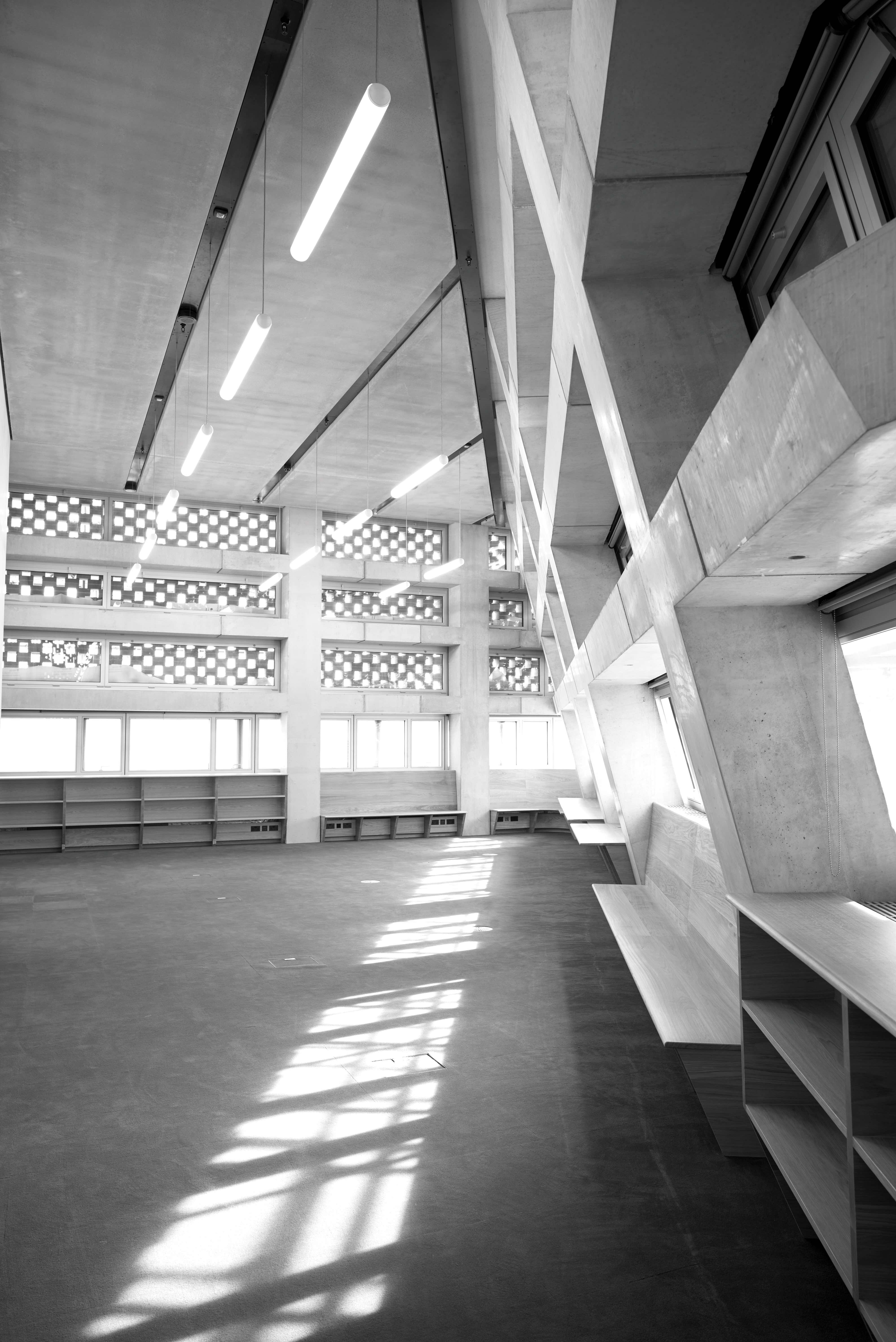
Outside of the galleries, the above-ground circulation spaces in the extension – along with the office and education spaces – are predominantly naturally ventilated. Max Fordham’s decision to use natural ventilation was, in part, because of the large areas of concrete in the extension’s soffits, walls and lift cores. ‘It is almost cathedral-like in the quantity of exposed mass,’ says Nutley.
To boost the performance of the thermal mass, the engineers embedded cooling pipework into the concrete floor slabs in the circulation, office and education areas. In fact, thousands of metres of pipework is installed in the precast concrete floor slabs, significantly enhancing their thermal-storage capability to help keep conditions comfortable for visitors.
The thermal mass is cooled at night. Outside air enters the spaces through high-level automated, opening windows on one side of the building, and exits on the opposite side. The opening windows are secure because – as well as being high up – most are located behind perforations in the brick façade.
Heat is removed from the floor slabs by running chilled water through the embedded coils at night. The system uses the low-grade chilled water extracted from the river gravel via the borehole system. ‘Cooling the slabs using the borehole water supplements the natural ventilation in summer, when visitor numbers and air temperatures are at their peak,’ says Nutley.
Away from the galleries, the majority of the services in the tower had to run within the floor void to maximise the amount of thermal mass in these areas. The sprinkler pipework – plus the lighting, fire alarm, security and data cabling – drop from the floor void, through the concrete slab integrating into the ‘slot detail’.
The slots are located between the precast concrete soffit planks, housing all the services. ‘It is an elegant solution; it looks simple, but was a very difficult coordination exercise.’
Buffer spaces have been designed to separate the carefully controlled environment of the galleries and the circulation spaces. ‘The problem with a gallery as popular as the Tate is that doors – which would be open for much of the time – cannot be used. Instead, buffer spaces are installed,’ says Nutley.
Project team
Client: Tate Modern
Building services engineer: Max Fordham
Architect: Herzog & de Meuron
Lighting: Arup
These rooms act as introductory areas, which visitors pass through when entering a gallery. They are over-pressurised with air, creating ‘a curtain’ between the two areas. ‘It is a zone where you cannot guarantee the environmental conditions,’ says Nutley.
The Switch House opened its doors to visitors in June. It is early days for the environmental systems but, over the course of a year, Max Fordham’s scheme is expected to use 50% less energy than a typical gallery – which should see the Tate meet its objective of taking a leading role in sustainability.