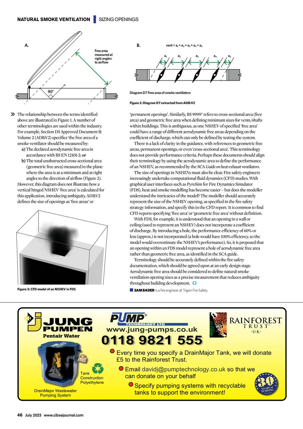


NATURAL SMOKE VENTILATION | SIZING OPENINGS A. B. Free area measured at right angles to airflow vent = a1 + a2 + a3 + a4 + a5 a1 a2 a3 a4 a5 Diagram D7 Free area of smoke ventilators Figure 2: Diagram D7 extracted from ADB:V2 The relationship between the terms identified above are illustrated in Figure 1. A number of other terminologies are used within the industry. For example, Section D5 Approved Document B: Volume 2 (ADB:V2) specifies the free area of a smoke ventilator should be measured by: a) The declared aerodynamic free area in accordance with BS EN 12101-2; or b) The total unobstructed cross-sectional area (geometric free area) measured in the plane where the area is at a minimum and at right angles to the direction of airflow (Figure 2). However, this diagram does not illustrate how a vertical hinged NSHEV free area is calculated for this application, introducing ambiguity. ADB:V2 defines the size of openings as free areas or permanent openings. Similarly, BS 99994 refers to cross-sectional area (free area) and geometric free area when defining minimum sizes for vents/shafts within buildings. This is ambiguous, as one NSHEV of specified free area could have a range of different aerodynamic free areas depending on the coefficient of discharge, which can only be defined by testing the system. There is a lack of clarity in the guidance, with references to geometric free areas, permanent openings, or even cross-sectional area. This terminology does not provide performance criteria. Perhaps these documents should align their terminology by using the aerodynamic area to define the performance of an NSHEV, as recommended by the SCA Guide on heat exhaust ventilators. The size of openings in NSHEVs must also be clear. Fire safety engineers increasingly undertake computational fluid dynamics (CFD) studies. With graphical user interfaces such as PyroSim for Fire Dynamics Simulator (FDS), heat and smoke modelling has become easier but does the modeller understand the intricacies of the model? The modeller should accurately represent the size of the NSHEV opening, as specified in the fire safety strategy information, and specify this in the CFD report. It is common to find CFD reports specifying free area or geometric free area without definition. With FDS, for example, it is understood that an opening in a wall or ceiling (used to represent an NSHEV) does not incorporate a coefficient of discharge. By introducing a hole, the performance efficiency of 60% or less (approx.) is not incorporated (a hole would have 100% efficiency, so the model would overestimate the NSHEVs performance). So, it is proposed that an opening within an FDS model represent a hole of aerodynamic free area rather than geometric free area, as identified in the SCA guide. Terminology should be accurately defined within the fire safety documentation, which should be agreed upon at an early design stage. Aerodynamic free area should be considered to define natural smoke ventilation opening sizes as a precise measurement that reduces ambiguity throughout building development. CJ Figure 3: CFD model of an NSHEV in FDS SAM BADER is a fire engineer at Trigon Fire Safety www.jung-pumps.co.uk 0118 9821 555 Every time you specify a DrainMajor Tank, we will donate 5 to the Rainforest Trust. Tank Construction Polyethylene DrainMajor Wastewater Pumping System 46 July 2023 www.cibsejournal.com Email davidj@pumptechnology.co.uk so that we can donate on your behalf Specify pumping systems with recyclable tanks to support the environment!