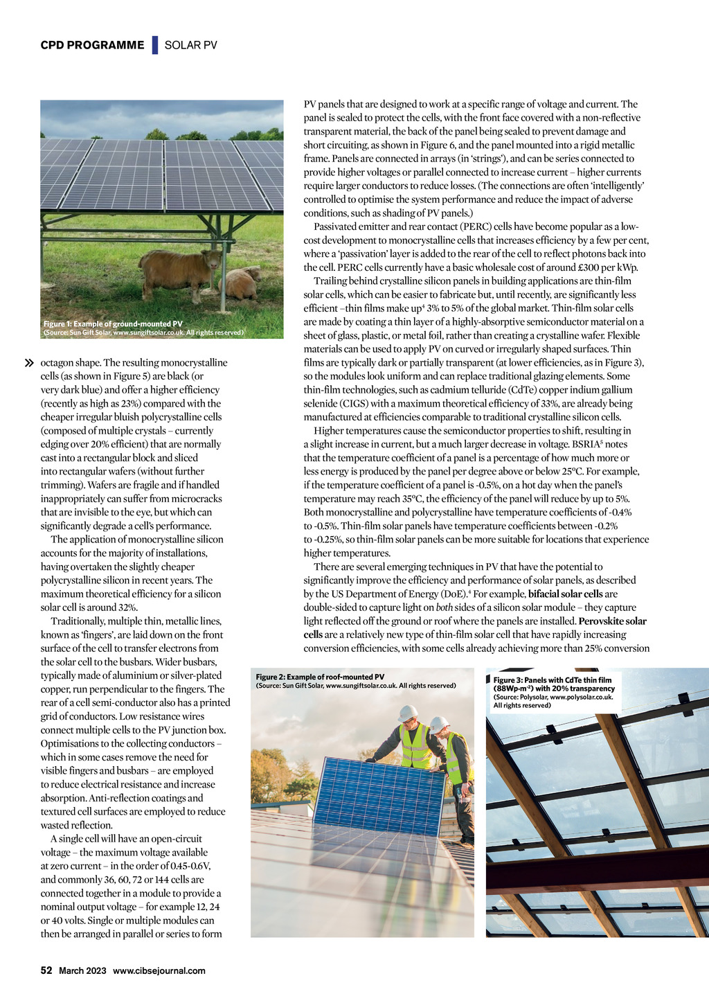
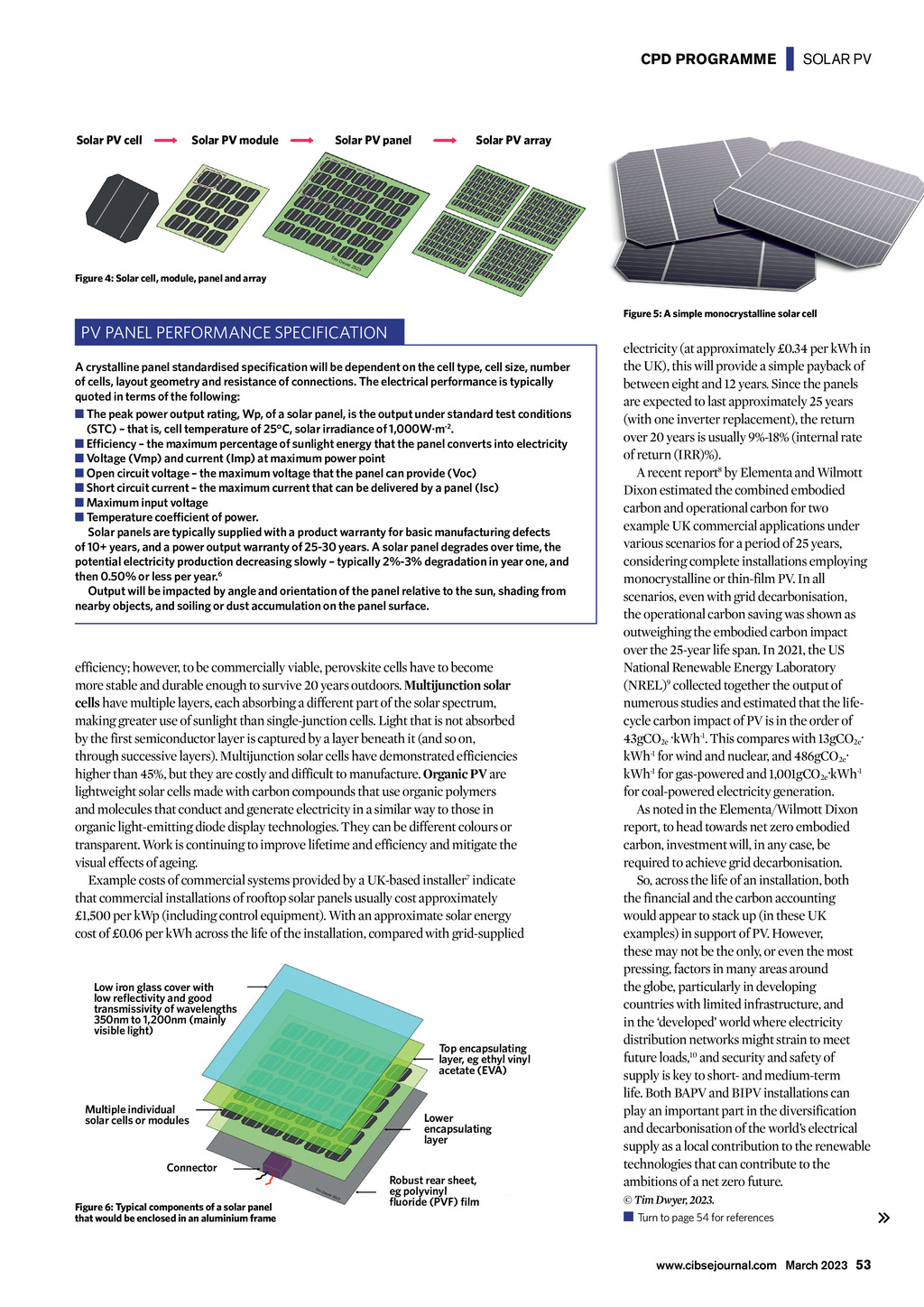

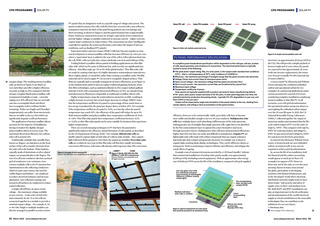
CPD PROGRAMME | SOLAR PV Figure 1: Example of ground-mounted PV (Source: Sun Gift Solar, www.sungiftsolar.co.uk. All rights reserved) octagon shape. The resulting monocrystalline cells (as shown in Figure 5) are black (or very dark blue) and offer a higher efficiency (recently as high as 23%) compared with the cheaper irregular bluish polycrystalline cells (composed of multiple crystals currently edging over 20% efficient) that are normally cast into a rectangular block and sliced into rectangular wafers (without further trimming). Wafers are fragile and if handled inappropriately can suffer from microcracks that are invisible to the eye, but which can significantly degrade a cells performance. The application of monocrystalline silicon accounts for the majority of installations, having overtaken the slightly cheaper polycrystalline silicon in recent years. The maximum theoretical efficiency for a silicon solar cell is around 32%. Traditionally, multiple thin, metallic lines, known as fingers, are laid down on the front surface of the cell to transfer electrons from the solar cell to the busbars. Wider busbars, typically made of aluminium or silver-plated copper, run perpendicular to the fingers. The rear of a cell semi-conductor also has a printed grid of conductors. Low resistance wires connect multiple cells to the PV junction box. Optimisations to the collecting conductors which in some cases remove the need for visible fingers and busbars are employed to reduce electrical resistance and increase absorption. Anti-reflection coatings and textured cell surfaces are employed to reduce wasted reflection. A single cell will have an open-circuit voltage the maximum voltage available at zero current in the order of 0.45-0.6V, and commonly 36, 60, 72 or 144 cells are connected together in a module to provide a nominal output voltage for example 12, 24 or 40 volts. Single or multiple modules can then be arranged in parallel or series to form 52 March 2023 www.cibsejournal.com PV panels that are designed to work at a specific range of voltage and current. The panel is sealed to protect the cells, with the front face covered with a non-reflective transparent material, the back of the panel being sealed to prevent damage and short circuiting, as shown in Figure 6, and the panel mounted into a rigid metallic frame. Panels are connected in arrays (in strings), and can be series connected to provide higher voltages or parallel connected to increase current higher currents require larger conductors to reduce losses. (The connections are often intelligently controlled to optimise the system performance and reduce the impact of adverse conditions, such as shading of PV panels.) Passivated emitter and rear contact (PERC) cells have become popular as a lowcost development to monocrystalline cells that increases efficiency by a few per cent, where a passivation layer is added to the rear of the cell to reflect photons back into the cell. PERC cells currently have a basic wholesale cost of around 300 per kWp. Trailing behind crystalline silicon panels in building applications are thin-film solar cells, which can be easier to fabricate but, until recently, are significantly less efficient thin films make up4 3% to 5% of the global market. Thin-film solar cells are made by coating a thin layer of a highly-absorptive semiconductor material on a sheet of glass, plastic, or metal foil, rather than creating a crystalline wafer. Flexible materials can be used to apply PV on curved or irregularly shaped surfaces. Thin films are typically dark or partially transparent (at lower efficiencies, as in Figure 3), so the modules look uniform and can replace traditional glazing elements. Some thin-film technologies, such as cadmium telluride (CdTe) copper indium gallium selenide (CIGS) with a maximum theoretical efficiency of 33%, are already being manufactured at efficiencies comparable to traditional crystalline silicon cells. Higher temperatures cause the semiconductor properties to shift, resulting in a slight increase in current, but a much larger decrease in voltage. BSRIA5 notes that the temperature coefficient of a panel is a percentage of how much more or less energy is produced by the panel per degree above or below 25C. For example, if the temperature coefficient of a panel is -0.5%, on a hot day when the panels temperature may reach 35C, the efficiency of the panel will reduce by up to 5%. Both monocrystalline and polycrystalline have temperature coefficients of -0.4% to -0.5%. Thin-film solar panels have temperature coefficients between -0.2% to -0.25%, so thin-film solar panels can be more suitable for locations that experience higher temperatures. There are several emerging techniques in PV that have the potential to significantly improve the efficiency and performance of solar panels, as described by the US Department of Energy (DoE).4 For example, bifacial solar cells are double-sided to capture light on both sides of a silicon solar module they capture light reflected off the ground or roof where the panels are installed. Perovskite solar cells are a relatively new type of thin-film solar cell that have rapidly increasing conversion efficiencies, with some cells already achieving more than 25% conversion Figure 2: Example of roof-mounted PV (Source: Sun Gift Solar, www.sungiftsolar.co.uk. All rights reserved) Figure 3: Panels with CdTe thin film (88Wp.m-2) with 20% transparency (Source: Polysolar, www.polysolar.co.uk. All rights reserved)