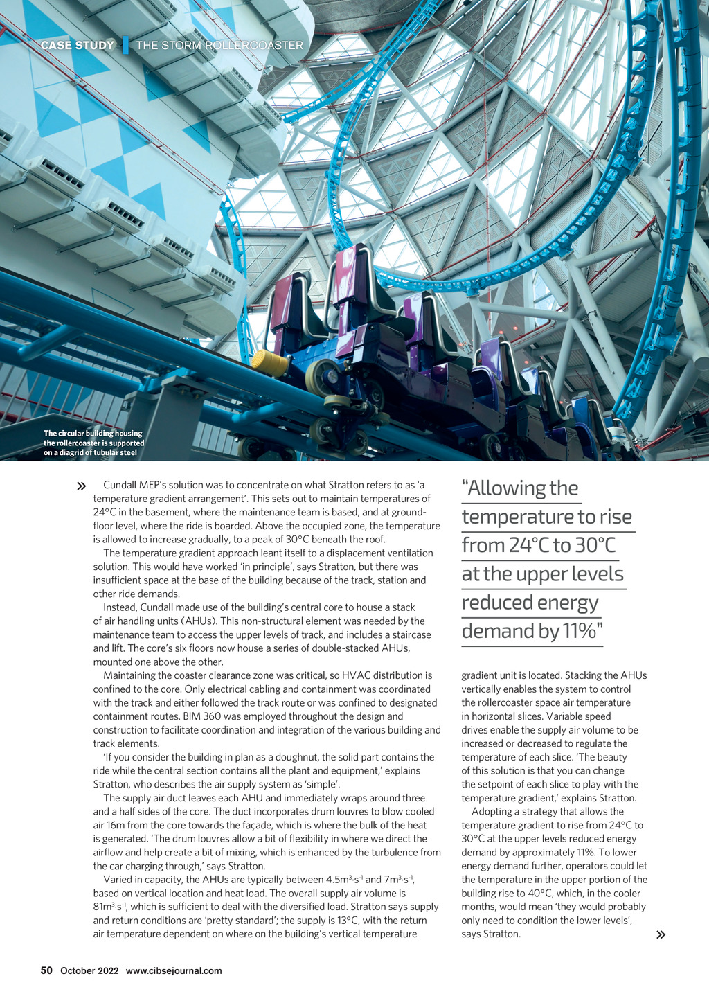
CASE STUDY | THE STORM ROLLERCOASTER The circular building housing the rollercoaster is supported on a diagrid of tubular steel Cundall MEPs solution was to concentrate on what Stratton refers to as a temperature gradient arrangement. This sets out to maintain temperatures of 24C in the basement, where the maintenance team is based, and at groundoor level, where the ride is boarded. Above the occupied zone, the temperature is allowed to increase gradually, to a peak of 30C beneath the roof. The temperature gradient approach leant itself to a displacement ventilation solution. This would have worked in principle, says Stratton, but there was insufcient space at the base of the building because of the track, station and other ride demands. Instead, Cundall made use of the buildings central core to house a stack of air handling units (AHUs). This non-structural element was needed by the maintenance team to access the upper levels of track, and includes a staircase and lift. The cores six oors now house a series of double-stacked AHUs, mounted one above the other. Maintaining the coaster clearance zone was critical, so HVAC distribution is conned to the core. Only electrical cabling and containment was coordinated with the track and either followed the track route or was conned to designated containment routes. BIM 360 was employed throughout the design and construction to facilitate coordination and integration of the various building and track elements. If you consider the building in plan as a doughnut, the solid part contains the ride while the central section contains all the plant and equipment, explains Stratton, who describes the air supply system as simple. The supply air duct leaves each AHU and immediately wraps around three and a half sides of the core. The duct incorporates drum louvres to blow cooled air 16m from the core towards the faade, which is where the bulk of the heat is generated. The drum louvres allow a bit of exibility in where we direct the airow and help create a bit of mixing, which is enhanced by the turbulence from the car charging through, says Stratton. Varied in capacity, the AHUs are typically between 4.5m3.s-1 and 7m3.s-1, based on vertical location and heat load. The overall supply air volume is 81m3.s-1, which is sufcient to deal with the diversied load. Stratton says supply and return conditions are pretty standard; the supply is 13C, with the return air temperature dependent on where on the buildings vertical temperature Allowing the temperature to rise from 24C to 30C at the upper levels reduced energy demand by 11% gradient unit is located. Stacking the AHUs vertically enables the system to control the rollercoaster space air temperature in horizontal slices. Variable speed drives enable the supply air volume to be increased or decreased to regulate the temperature of each slice. The beauty of this solution is that you can change the setpoint of each slice to play with the temperature gradient, explains Stratton. Adopting a strategy that allows the temperature gradient to rise from 24C to 30C at the upper levels reduced energy demand by approximately 11%. To lower energy demand further, operators could let the temperature in the upper portion of the building rise to 40C, which, in the cooler months, would mean they would probably only need to condition the lower levels, says Stratton. 50 October 2022 www.cibsejournal.com CIBSE Oct 22 pp50-52, 54 Storm Rollercoaster Supp.indd 50 26/09/2022 14:54