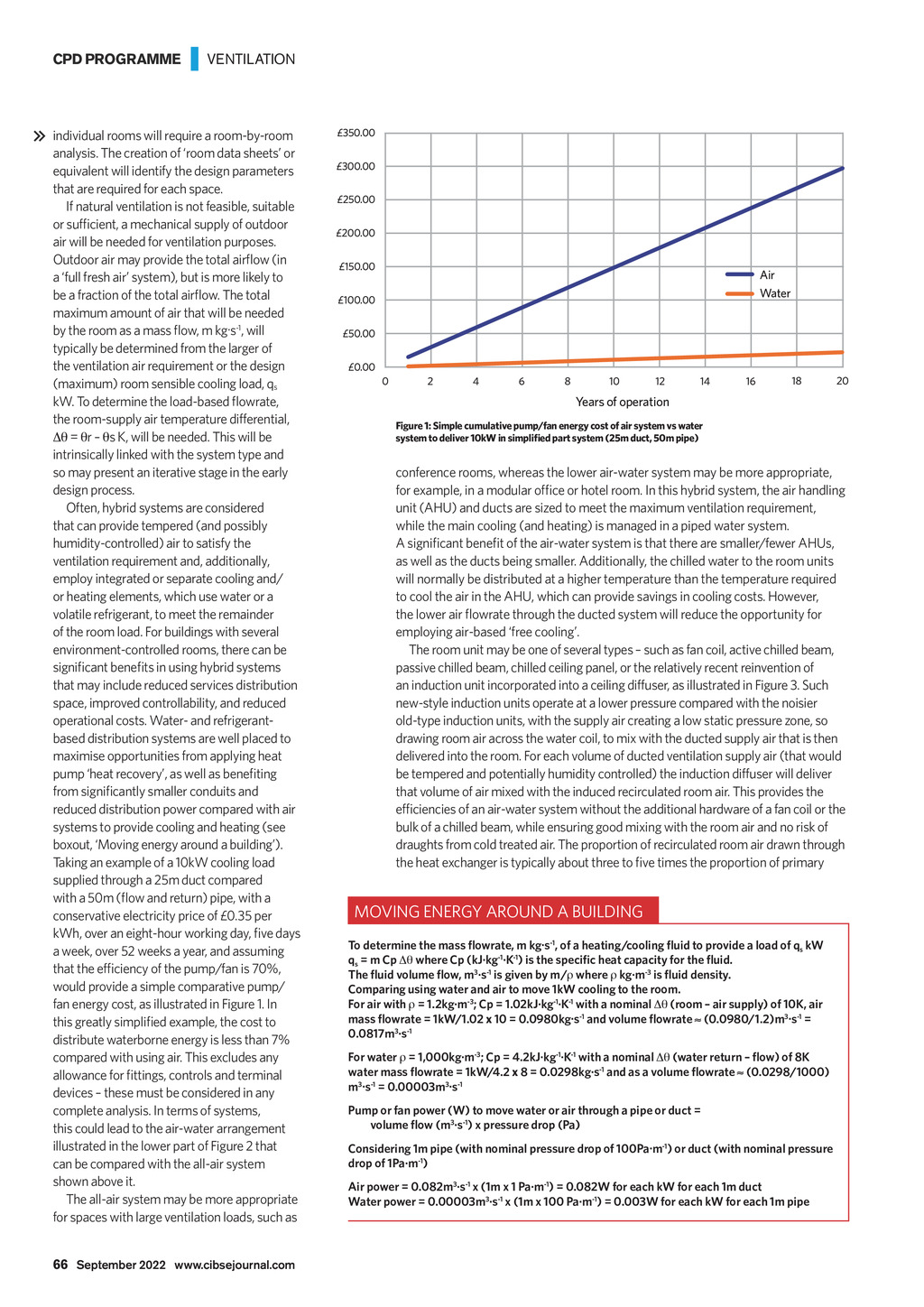
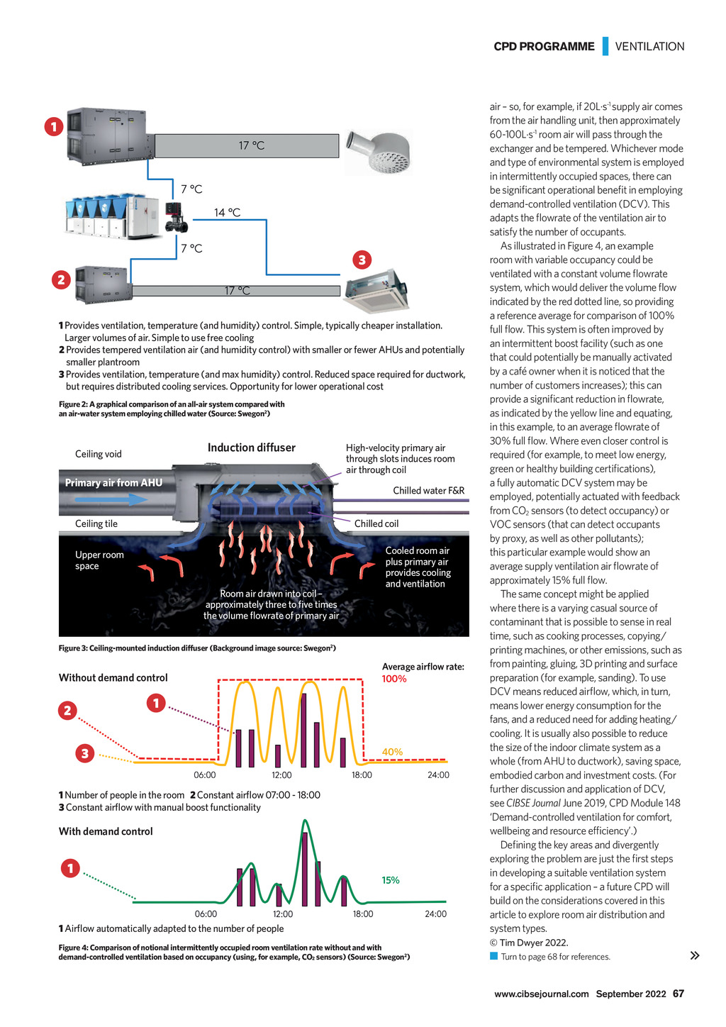

CPD PROGRAMME | VENTILATION individual rooms will require a room-by-room analysis. The creation of room data sheets or equivalent will identify the design parameters that are required for each space. If natural ventilation is not feasible, suitable or sufficient, a mechanical supply of outdoor air will be needed for ventilation purposes. Outdoor air may provide the total airflow (in a full fresh air system), but is more likely to be a fraction of the total airflow. The total maximum amount of air that will be needed by the room as a mass flow, m kg.s-1, will typically be determined from the larger of the ventilation air requirement or the design (maximum) room sensible cooling load, qs kW. To determine the load-based flowrate, the room-supply air temperature differential, = r s K, will be needed. This will be intrinsically linked with the system type and so may present an iterative stage in the early design process. Often, hybrid systems are considered that can provide tempered (and possibly humidity-controlled) air to satisfy the ventilation requirement and, additionally, employ integrated or separate cooling and/ or heating elements, which use water or a volatile refrigerant, to meet the remainder of the room load. For buildings with several environment-controlled rooms, there can be significant benefits in using hybrid systems that may include reduced services distribution space, improved controllability, and reduced operational costs. Water- and refrigerantbased distribution systems are well placed to maximise opportunities from applying heat pump heat recovery, as well as benefiting from significantly smaller conduits and reduced distribution power compared with air systems to provide cooling and heating (see boxout, Moving energy around a building). Taking an example of a 10kW cooling load supplied through a 25m duct compared with a 50m (flow and return) pipe, with a conservative electricity price of 0.35 per kWh, over an eight-hour working day, five days a week, over 52 weeks a year, and assuming that the efficiency of the pump/fan is 70%, would provide a simple comparative pump/ fan energy cost, as illustrated in Figure 1. In this greatly simplified example, the cost to distribute waterborne energy is less than 7% compared with using air. This excludes any allowance for fittings, controls and terminal devices these must be considered in any complete analysis. In terms of systems, this could lead to the air-water arrangement illustrated in the lower part of Figure 2 that can be compared with the all-air system shown above it. The all-air system may be more appropriate for spaces with large ventilation loads, such as 350.00 300.00 250.00 200.00 150.00 Air Water 100.00 50.00 0.00 0 2 4 6 8 10 12 14 16 18 20 Years of operation Figure 1: Simple cumulative pump/fan energy cost of air system vs water system to deliver 10kW in simplified part system (25m duct, 50m pipe) conference rooms, whereas the lower air-water system may be more appropriate, for example, in a modular office or hotel room. In this hybrid system, the air handling unit (AHU) and ducts are sized to meet the maximum ventilation requirement, while the main cooling (and heating) is managed in a piped water system. A significant benefit of the air-water system is that there are smaller/fewer AHUs, as well as the ducts being smaller. Additionally, the chilled water to the room units will normally be distributed at a higher temperature than the temperature required to cool the air in the AHU, which can provide savings in cooling costs. However, the lower air flowrate through the ducted system will reduce the opportunity for employing air-based free cooling. The room unit may be one of several types such as fan coil, active chilled beam, passive chilled beam, chilled ceiling panel, or the relatively recent reinvention of an induction unit incorporated into a ceiling diffuser, as illustrated in Figure 3. Such new-style induction units operate at a lower pressure compared with the noisier old-type induction units, with the supply air creating a low static pressure zone, so drawing room air across the water coil, to mix with the ducted supply air that is then delivered into the room. For each volume of ducted ventilation supply air (that would be tempered and potentially humidity controlled) the induction diffuser will deliver that volume of air mixed with the induced recirculated room air. This provides the efficiencies of an air-water system without the additional hardware of a fan coil or the bulk of a chilled beam, while ensuring good mixing with the room air and no risk of draughts from cold treated air. The proportion of recirculated room air drawn through the heat exchanger is typically about three to five times the proportion of primary MOVING ENERGY AROUND A BUILDING To determine the mass flowrate, m kg.s-1, of a heating/cooling fluid to provide a load of qs kW qs = m Cp where Cp (kJ.kg-1.K-1) is the specific heat capacity for the fluid. The fluid volume flow, m3.s-1 is given by m/ where kg.m-3 is fluid density. Comparing using water and air to move 1kW cooling to the room. For air with = 1.2kg.m-3; Cp = 1.02kJ.kg-1.K-1 with a nominal (room air supply) of 10K, air mass flowrate = 1kW/1.02 x 10 = 0.0980kg.s-1 and volume flowrate (0.0980/1.2)m3.s-1 = 0.0817m3.s-1 For water = 1,000kg.m-3; Cp = 4.2kJ.kg-1.K-1 with a nominal (water return flow) of 8K water mass flowrate = 1kW/4.2 x 8 = 0.0298kg.s-1 and as a volume flowrate (0.0298/1000) m3.s-1 = 0.00003m3.s-1 Pump or fan power (W) to move water or air through a pipe or duct = volume flow (m3.s-1) x pressure drop (Pa) Considering 1m pipe (with nominal pressure drop of 100Pa.m-1) or duct (with nominal pressure drop of 1Pa.m-1) Air power = 0.082m3.s-1 x (1m x 1 Pa.m-1) = 0.082W for each kW for each 1m duct Water power = 0.00003m3.s-1 x (1m x 100 Pa.m-1) = 0.003W for each kW for each 1m pipe 66 September 2022 www.cibsejournal.com CIBSE Sept 22 pp65-68 CPD 202 Supp.indd 66 26/08/2022 15:47