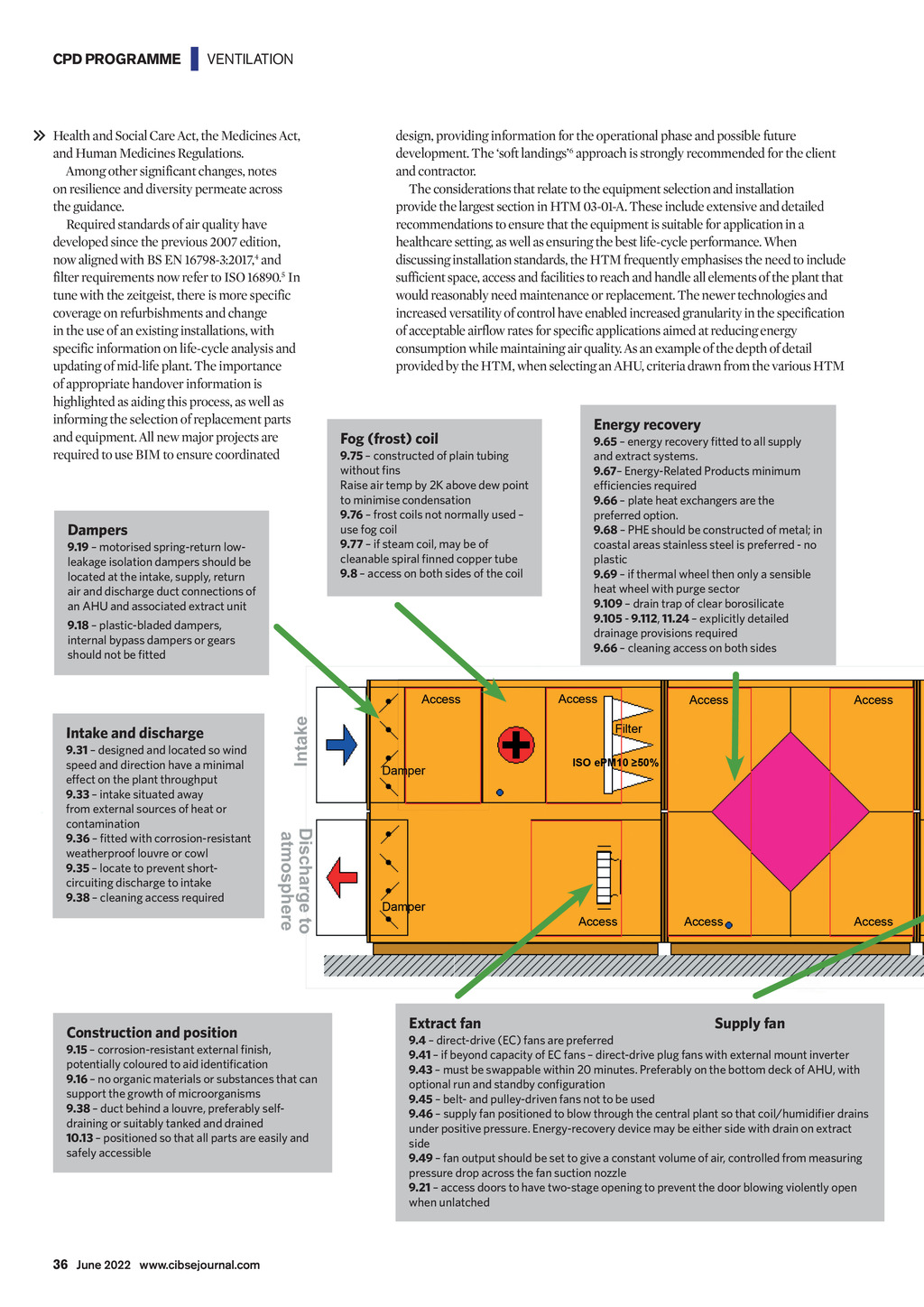
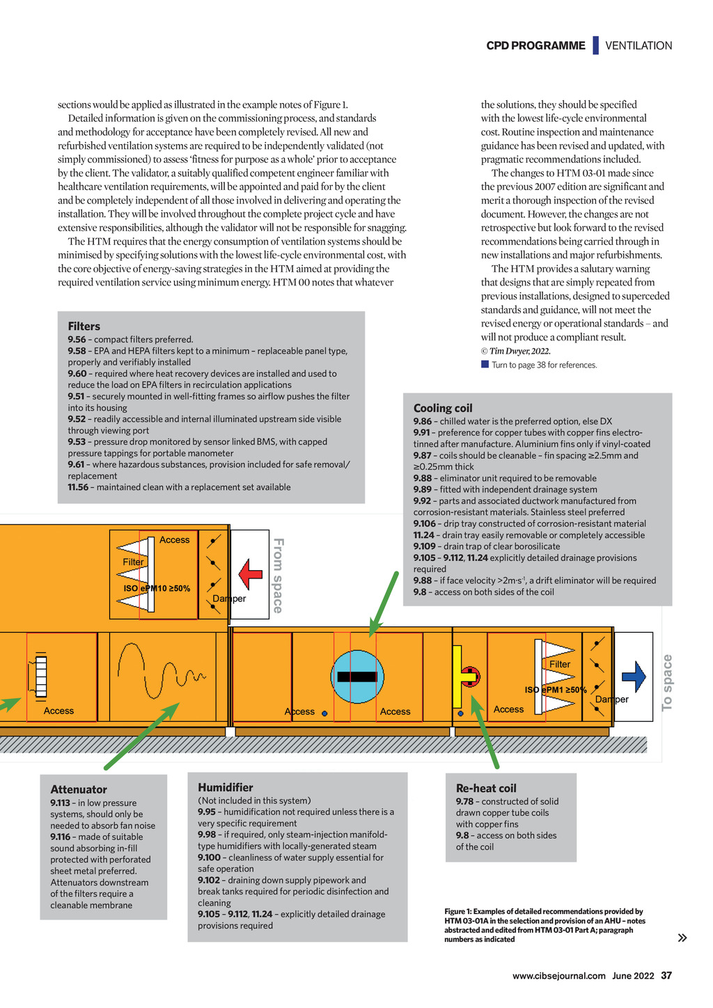
CPD PROGRAMME | VENTILATION Health and Social Care Act, the Medicines Act, and Human Medicines Regulations. Among other significant changes, notes on resilience and diversity permeate across the guidance. Required standards of air quality have developed since the previous 2007 edition, now aligned with BS EN 16798-3:2017,4 and filter requirements now refer to ISO 16890.5 In tune with the zeitgeist, there is more specific coverage on refurbishments and change in the use of an existing installations, with specific information on life-cycle analysis and updating of mid-life plant. The importance of appropriate handover information is highlighted as aiding this process, as well as informing the selection of replacement parts and equipment. All new major projects are required to use BIM to ensure coordinated Dampers 9.19 motorised spring-return lowleakage isolation dampers should be located at the intake, supply, return air and discharge duct connections of an AHU and associated extract unit design, providing information for the operational phase and possible future development. The soft landings6 approach is strongly recommended for the client and contractor. The considerations that relate to the equipment selection and installation provide the largest section in HTM 03-01-A. These include extensive and detailed recommendations to ensure that the equipment is suitable for application in a healthcare setting, as well as ensuring the best life-cycle performance. When discussing installation standards, the HTM frequently emphasises the need to include sufficient space, access and facilities to reach and handle all elements of the plant that would reasonably need maintenance or replacement. The newer technologies and increased versatility of control have enabled increased granularity in the specification of acceptable airflow rates for specific applications aimed at reducing energy consumption while maintaining air quality. As an example of the depth of detail provided by the HTM, when selecting an AHU, criteria drawn from the various HTM Fog (frost) coil 9.75 constructed of plain tubing without fins Raise air temp by 2K above dew point to minimise condensation 9.76 frost coils not normally used use fog coil 9.77 if steam coil, may be of cleanable spiral finned copper tube 9.8 access on both sides of the coil 9.18 plastic-bladed dampers, internal bypass dampers or gears should not be fitted Energy recovery 9.65 energy recovery fitted to all supply and extract systems. 9.67 Energy-Related Products minimum efficiencies required 9.66 plate heat exchangers are the preferred option. 9.68 PHE should be constructed of metal; in coastal areas stainless steel is preferred - no plastic 9.69 if thermal wheel then only a sensible heat wheel with purge sector 9.109 drain trap of clear borosilicate 9.105 - 9.112, 11.24 explicitly detailed drainage provisions required 9.66 cleaning access on both sides Intake and discharge 9.31 designed and located so wind speed and direction have a minimal effect on the plant throughput 9.33 intake situated away from external sources of heat or contamination 9.36 fitted with corrosion-resistant weatherproof louvre or cowl 9.35 locate to prevent shortcircuiting discharge to intake 9.38 cleaning access required Construction and position 9.15 corrosion-resistant external finish, potentially coloured to aid identification 9.16 no organic materials or substances that can support the growth of microorganisms 9.38 duct behind a louvre, preferably selfdraining or suitably tanked and drained 10.13 positioned so that all parts are easily and safely accessible Extract fan Supply fan 9.4 direct-drive (EC) fans are preferred 9.41 if beyond capacity of EC fans direct-drive plug fans with external mount inverter 9.43 must be swappable within 20 minutes. Preferably on the bottom deck of AHU, with optional run and standby configuration 9.45 belt- and pulley-driven fans not to be used 9.46 supply fan positioned to blow through the central plant so that coil/humidifier drains under positive pressure. Energy-recovery device may be either side with drain on extract side 9.49 fan output should be set to give a constant volume of air, controlled from measuring pressure drop across the fan suction nozzle 9.21 access doors to have two-stage opening to prevent the door blowing violently open when unlatched 36 June 2022 www.cibsejournal.com CIBSE June 22 pp35-38 CPD 197.indd 36 27/05/2022 15:49