
Sponsor of this month's CPD
The traditional method of distributing heated water from a boiler to building heating system circuits uses a low-loss header to connect the primary boiler circuit with the secondary distribution.
There are, however, circumstances where it is advantageous hydraulically to decouple the primary circuit of the boiler from the secondary circuits of the heating systems, and this can be achieved by replacing the low-loss header with a plate heat exchanger.
This article considers the common types of plate heat exchanger that are used in building services systems, and discusses how they can usefully be applied in place of the traditional low-loss header in existing systems when new, high-efficiency boilers are installed.
The main types of plate heat exchangers (PHEs) used in building services systems are either gasketed (demountable) units or complete assemblies that have been brazed. The brazed units were originally developed to allow extreme operational pressures and temperatures, but are now commonly applied across many applications. PHEs are available in a range of sizes, capable of transferring from only a few kilowatts (kW) of heat up to several megawatts (MW).
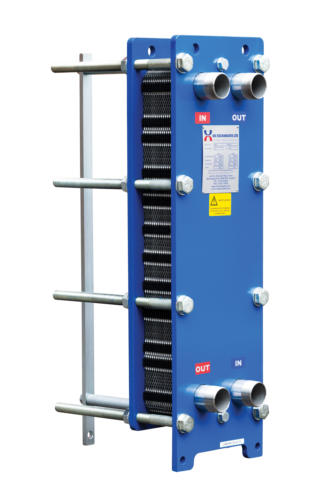
Figure 1: An example of a demountable, gasketed plate heat exchanger (Source: Vaillant/UK Exchangers)
Gasketed PHEs – also known as plate-and-frame heat exchangers – are made of multiple, embossed stainless steel plates bolted together, with interleaving sealing gaskets, positioned between two end frames (as shown in Figure 1). The frames and mounting assembly are designed so they can be taken apart, and rebuilt, for cleaning and inspection. Gaskets between the plates separate the two flows and create the external seal. Gasket failure does not cause the two flows to mix – the gasket is arranged so that such leaks will go to atmosphere. Twin-walled plates are available for applications where it is critical that the two flows should not mix – as might be appropriate for domestic hot water usage. The plates are normally stainless steel and, in the brazed version, would be jointed with copper. The more robust – and lower cost – brazed heat exchangers (such as that shown in Figure 2) are sealed components, so they cannot be deconstructed for maintenance.
Hot fluid flows on one side of each plate, and cooler fluid counterflows on the other side. Ports at each corner of the end plates act as headers for the fluid. One fluid travels in the alternate gaps (or channels) to the other, and the specific direction of the flow will be dependent on the individual manufacturer’s design. The channels in the PHE are formed so that, even at low values of simple Reynolds number, there is turbulent flow, so – in conjunction with the thin, high-conductivity stainless steel plates – they have very good heat-transfer characteristics. Compared with a shell-and-tube heat exchanger, the heat transfer is equivalent to four or five times greater per unit area.1
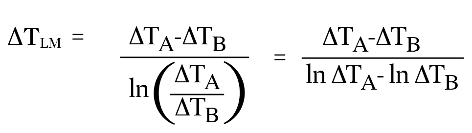
The heat transferred from one flowing liquid to the other through a plate heat exchanger can be determined from U A ∆TLM where U is the average thermal transmittance from one flow to the other (W·m-2·K-1), A is the overall heat transfer area (m2) and ∆TLM is the log mean temperature difference of the two flows.
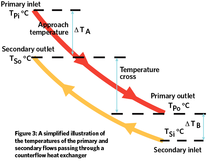
∆TLM is determined from the entering and leaving primary and secondary temperatures. For the counterflow plate heat exchanger illustrated in Figure 2 and Figure 3,
As well as this relationship being applied to assess PHE design capacities, it is also useful to determine how adequately the heat exchanger is performing during operation – assessing whether it is excessively obstructed or fouled – by taking measurements of temperatures and comparing ∆TLM with that of when it was originally commissioned. The plate heat exchange design is able to achieve a large temperature cross and, potentially, a 1K temperature approach because of the counterflow fluid path and high U.1
When PHEs are selected, it is important to obtain advice from the manufacturer, not only to determine basic sizing parameters, but also to take proper account of ‘fouling’ – the accumulation of deposited materials on the plates, which will relate to both the design of the corrugations in the plates and the type of fluid. If a PHE is correctly selected, then the fouling in heating water heat exchangers is likely to be very small, because of the turbulent flow that is required for proper operation. By mistakenly overestimating the likely fouling (and the consequent reduction in the value of U) the PHE will be oversized and the resulting water velocity could be lower than ideal – so, ironically, encouraging increased levels of fouling. In some building applications, such as those using cooling tower water, potential fouling can be more challenging and can include crystallisation, sedimentation, and organic material growth.
PHEs require very little maintenance because the high-velocity and turbulent flow of the fluid in the channels keeps surfaces clear from fouling. Strainers (filters) can be installed in the pipeline before the heat exchanger to prolong its working effectiveness, but must be periodically flushed clean as part of the maintenance programme. If, however, larger particles become lodged in the small spaces between the plates – and so obstruct the flow – back-flushing can be used to attempt to remove the obstructing material.
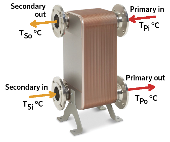
Figure 2: An example of a copper-brazed stainless steel plate heat exchanger, approximately 500mm tall and 270mm wide, that can provide heat exchange of 240kW to 1MW (Photo source: Vaillant)
To maintain operational effectiveness, the dismantling and cleaning of gasketed PHEs is often scheduled as part of an annual maintenance plan. Gaskets on large PHEs are costly to replace, and in-situ maintenance must ensure that the plates are evenly loaded, and kept square and flat – by methodically tightening the bolts to an appropriate torque to secure the pressure plate – to ensure longevity of successful operation. Chemical or ultrasonic cleaning may be required to remove dirt and debris in brazed PHEs after a period of operation. This can be done in situ, if appropriate valve arrangements have been installed.
Applications of PHEs in building heating systems
PHEs are already commonplace in a number of applications in building systems. They are most often found in combination boilers, where brazed PHEs are used to divert heat from the primary heating circuit to the instantaneous flow of domestic hot water. In commercial continuous flow heating and hot water systems, PHE primaries can be fed from low-, medium- or high-temperature heat sources, including steam. They also form the core of the heat interface unit (HIU), as used for district heating schemes to supply heat to end users.2
They are increasingly applied to refurbishment projects where, throughout the life of the system, there will be degradation of the pipework and fittings that will cause particulate matter and limescale (calcium carbonate) to accumulate within the system. Methods are available to remove particulate matter – such as filters, cyclone-type separators and magnetic sludge removers – but, on an older system, it is particularly challenging to ensure the absence of all particulate matter, even after undertaking a comprehensive cleaning and flushing operation.
The resulting boiler performance can be affected. For example, partial blockages of the waterways can produce ‘hot spots’ within the boiler that will affect performance to such an extent that significant maintenance would be required. Older cast-iron boilers with large waterways are less susceptible, and could often cope with such conditions where particulate matter could accumulate at the bottom of the channels without causing a major obstruction. Newer, high-efficiency boilers have smaller waterways, so there is less room within the system for dirt and debris to collect without adversely affecting performance. Condensing boilers are generally installed as part of a sealed, pressurised system, but many older, open-vented systems are not suitable for conversion to sealed operation.
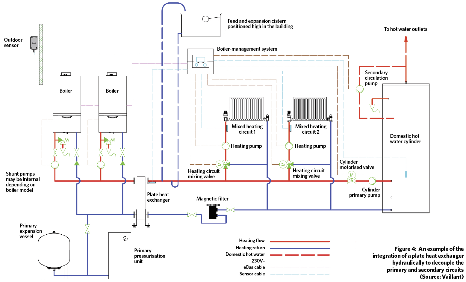
A practical solution is to leave the existing (secondary) system open-vented, while hydraulically decoupling the primary circuit using a PHE, to provide a protected, pressurised primary circuit for the new boiler. The PHE would typically replace the traditional low-loss header, the principal function of which is hydraulically to separate the primary and secondary circuits, as shown in Figure 4.
It is important that the heat exchanger is sized correctly, not only to supply the required heat to the secondary circuit, but also to ensure that the hydraulic resistance can be accommodated by the primary and the secondary system pumps. The pressure drop on the secondary side of a PHE is likely to be between 10kPa and 30kPa. This compares with less than 10Pa in a low-loss header. To place this in context, a typical heating pipework system would normally be sized at a pressure drop of 200 to 300Pa·m-1, so the pressure drop through the PHE is equivalent to approximately 40m to 120m of straight heating pipework. The primary side pressure loss of the PHEs should be low enough for a single boiler primary (or ‘shunt’) pump to be able to circulate the water. A higher pressure drop across the PHE or an increase in the design ∆TLM will usually result in a smaller heat exchanger.
Most modern high-efficiency boilers are designed to operate with a fixed operating temperature differential of 20K – for example 80°C/60°C or, for condensing operation, 70°C/50°C or 60°C/40°C. However, older heating systems were often designed to operate on an 11K differential – typically 82°C /71°C or 180°F/160°F. The PHE cannot, of course, increase the temperature of the secondary flow above that of the primary. However, the temperature of the secondary flow can reach to within 2K and 5K of that of the primary flow. In practice, the resulting reduced secondary-water mean temperature – compared with that of the original system design – does not cause problems in normal operation, as many old systems and their heat emitters are oversized, or buildings have undergone some refurbishment, so reducing the heating load from that when the building was originally built. The use of a PHE does not preclude the possibility of running the secondary system with a greater ∆T to allow condensing operation of the boiler, but this would require that the existing heat emitters were able to meet the building loads at a lower mean water temperature.
Separating the primary and secondary circuits will mean that, during boiler maintenance, the requirement for draining down will be reduced, and the volumes of replacement, treated make-up water will be lower for the pressurised system, making maintenance simpler, quicker and less costly. The recommissioning of the pressurised system will also be completed more swiftly, as there will be less risk of air being introduced to the system because of the smaller system pipe network.
Properly applied and installed, PHEs can ease the integration and ensure effective operation of new boilers with existing systems. Using the PHE to decouple new high-efficiency pressurised boilers from the main distribution system can protect new boilers from the contamination likely to exist in legacy systems. This also allows the existing pipework infrastructure to remain in place, creating the opportunity for staged refurbishment while keeping the primary heat source in operation. Removing the boiler from the main distribution system will allow more control over the water quality circulating in the boilers, so improving boiler life-cycle operational efficiency, reducing maintenance and potential breakdowns, and maximising useful life.
The use of PHEs in commercial heating systems is reportedly growing3 as awareness about potential applications and benefits increases. There is a dearth of authoritative guidance in this specific application of PHE as a replacement for traditional low-loss headers, so the suggested benefits discussed here are reliant on the experience of manufacturers. Just a few years ago, the use of such technology in this application was extremely rare, but it has now expanded to the stage where a major manufacturer3 reports that 50% of its commercial applications, where replacement boilers employ existing pipework, now include PHEs in the specification. This range of applications includes hotels, leisure complexes, schools and residential homes.
© Tim Dwyer, 2017.