
The two common fan types used in building services for ducted systems are generically referred to as centrifugal and axial fans – the name deriving from the defining direction of air flow through the fan. These two types are themselves split into a number of subtypes that have been developed to provide particular volume flow/pressure characteristics, as well as other operational attributes (including size, noise, vibration, cleanability, maintainability and robustness). This CPD unit will consider selected aspects of these fans, and to complement the article there is much good-quality detailed material freely available (see list at the end of this article). This article will attempt to include areas that may not typically be in many of the other general sources.
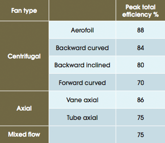
Table 1: US and European published peak fan efficiency data for fans >600mm in diameter
Some of the more frequently encountered types of fan used in HVAC are listed in Table 1, together with indicative peak efficiencies that have been collected1 from data published by a range of US and European manufacturers. In addition to these, the ‘plug’ fan (that is actually a variant of the centrifugal fan) has seen rising popularity in recent years.
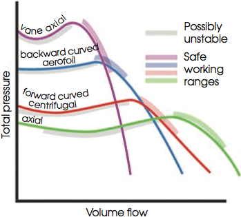
Figure 1: Generic fan curves. Real fans can differ widely from these simplified curves
Characteristic fan curves are shown in Figure 1. These are exaggerated, idealised curves, and real fans may well differ from these; however, they are likely to exhibit similar attributes. This includes the areas of instability that are due to hunting, where the fan can flip between two possible flowrates at the same pressure or as a consequence of the fan stalling (see Stalling of air flow box). Manufacturers should also identify preferred ‘safe’ working ranges in their literature.
Centrifugal fans
With centrifugal fans, the air enters the impeller along its axis, then it is discharged radially from the impeller with the centrifugal motion. These fans are capable of generating both high pressures and high volume flowrates. The majority of traditional centrifugal fans are enclosed in a scroll type housing (as in Figure 2) that acts to direct the moving air and efficiently convert the kinetic energy to static pressure. To move more air, the fan can be designed with a ‘double width double inlet’ impeller, allowing air to enter on both sides of the casing.
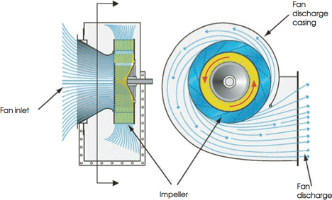
Figure 2: Centrifugal fan in scroll casing, with a backward inclined impeller (Source: CIBSE TM42:2006)
There are a number of shapes of blades that can make up the impeller, with the main types being forward curved and backward curved – the shape of the blade will determine its performance, potential efficiency and the shape of the characteristic fan curve. The other factors that will affect the fan’s efficiency are the width of the impeller wheel, the clearance space between the inlet cone and the rotating impeller, and the area used the discharge the air from the fan (the so-called ‘blast area’).
This type of fan has been traditionally driven by a motor with a belt and pulley arrangement. However, with the improvement in electronic speed controls and the increased availability of electronically commutated (‘EC’ or brushless) motors, direct drives are becoming more frequently used. This not only removes the inefficiencies inherent in a belt drive (that may be anything from 2% to more than 10%, depending on maintenance2) but is also likely to lessen vibration, reduce maintenance (fewer bearings and cleaning requirements) and make the assembly more compact.
Backward curved centrifugal fans
Backward curved (or ‘inclined’) fans are characterised by blades that tilt away from the direction of rotation. They can reach efficiencies of towards 90% when using aerofoil blades, as shown in Figure 3, or with plain blades shaped in three dimensions, and slightly less when using plain curved blades, and less again when using simple flat plate backward inclined blades. The air leaves the tips of the impeller at relatively low velocity, so the friction losses within the casing are low and air-generated noise is also low. They may stall at the extremes of the operating curve. Relatively wider impellers will provide greatest efficiencies, and can readily employ the more substantial aerofoil profiled blades. Slim impellers will show little benefit from using aerofoils so tend to use flat plate blades. Backward curved fans are particularly noted for their capacity to produce high pressures combined with low noise, and have a non- overloading power characteristic – this means that as the resistance reduces in a system and the flowrate increases the power drawn by the electrical motor will reduce. The construction of backward curved fans is likely to be more robust and rather heavier than the less efficient forward curved fan. The relatively slow air velocity of the air across the blades can allow the accumulation of contaminants (such as dust and grease).
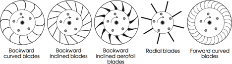
Figure 3: Illustration of centrifugal fan impellers
Forward curved centrifugal fans
Forward curved fans are characterised by a large number of forward curved blades. As they typically produce lower pressures, they are smaller, lighter and cheaper than the equivalent powered backward curved fan. As shown in Figure 3 and Figure 4, this type of fan impeller will include 20-plus blades that can be as simple as being formed from a single metal sheet. Improved efficiencies are obtained in larger sizes with individual formed blades. The air leaves the blade tips with a high tangential velocity, and this kinetic energy must be converted to static pressure in the casing – this detracts from the efficiency. They are typically used for low to medium air volumes at low pressure (normally <1.5kPa), and have a relatively low efficiency of below 70%. The scroll casing is particularly important to achieve the best efficiency, as the air leaves the tip of the blades at high velocity and is used to effectively convert the kinetic energy into static pressure. They run at low rotational speeds and, hence, mechanical generated noise levels tend to be less than higher- speed backward curved fans. The fan has an overloading power characteristic when operating against low system resistances.
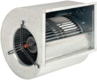
Figure 4: Forward curved centrifugal fan with integral motor (Source: EBMpapst)
These fans are not suitable where, for example, the air is heavily contaminated with dust or carries entrained grease droplets.
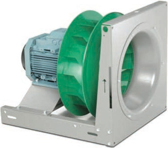
Figure 5: Example of direct driven plug fan with backward curved blades (Source: Fläkt Woods)
Radial bladed centrifugal fans
The radial bladed centrifugal fan has the benefit of being able to move contaminated air particles and at high pressures (in the order of 10kPa) but, running at high speeds, it is very noisy and inefficient (<60%) and so should not be used for general purpose HVAC. It also suffers from an overloading power characteristic – as the system resistance is reduced (maybe by volume control dampers opening), the motor power will rise and, depending on the motor size, may possibly ‘overload’.
Plug fans
Instead of being mounted in a scroll casing, these purpose-designed centrifugal impellers can be used directly in the casing of the air-handling unit (or, indeed, in any duct or plenum), and their initial cost is likely to be lower than housed centrifugal fans. Known as ‘plenum’, ‘plug’ or simply ‘unhoused’ centrifugal fans, these can provide some space advantages but at the price of lost operating efficiency (with the best efficiencies being similar to that for housed forward curved centrifugal fans). The fans will draw air in through the inlet cone (in the same way as a housed fan) but then discharge the air radially around the whole 360° outer circumference of the impeller. They can provide a great flexibility of outlet connections (from the plenum), meaning that there may be less need for adjacent bends or sharp transitions in the ductwork that would themselves add to the system pressure drop (and, hence, additional fan power). Overall system efficiency may be improved by using bell mouth entries to the ducts leaving the plenum. One of the benefits of the plug fan is its improved acoustic performance, largely resulting from the sound absorption within the plenum and the lack of ‘direct sight’ paths from the impeller into the mouth of the ductwork. The efficiency will be very dependent on the fan’s location within the plenum and the relationship of the fan to its outlet – the plenum being used to convert the kinetic energy in the air and so increase the static pressure. Substantially different performance and different stabilities of operation will depend on the impeller type – mixed flow impellers (providing a combination of radial and axial flow) have been used to overcome flow problems resulting from the strong radial air flow pattern created using simple centrifugal impellers3.
For smaller units, their compact design is often complemented through the use of readily controllable EC motors.
Axial fans
In axial flow fans, the air passes through the fan in line with the axis of rotation (as shown in the simple tube axial fan of Figure 6) – the pressurisation being produced by aerodynamic lift (similar to an aircraft wing). These can be comparatively compact, low cost and lightweight, particularly suited to moving air against relatively low pressures, so are frequently used in extract systems where the pressure drops are lower than supply systems – the supply normally including the pressure drop of all the air conditioning components in the air handling unit. When the air leaves a simple axial fan, it will be swirling due to the rotation imparted on the air as it passes through the impeller – the performance of the fan may be improved significantly by downstream guide vanes to recover the swirl, as in the vane axial fan shown in Figure 7. The efficiency of an axial fan is affected by the shape of the blade, the distance between the tip of the blade and the surrounding case, and the swirl recovery. The pitch of the blade can be altered to efficiently vary the fan’s output. By reversing the rotation of axial fans, the airflow can also be reversed – although the fan will be designed to work in the principal direction.
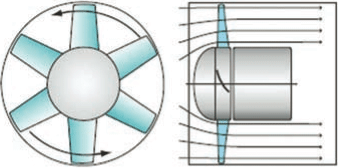
Figure 6: A tube axial flow fan (Source: GPG383)
The characteristic curve for axial fans has a stall region that can make them unsuitable for systems with a widely varying range of operating conditions, although they have the benefit of a non- overloading power characteristic.
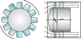
Figure 7: A vane axial flow fan (Source: GPG383)
Vane axial fans can be as efficient as backward curved centrifugal fans, and are able to produce high flows at reasonable pressures (typically around 2kPa), although they are likely to create more noise.
The mixed flow fan is a development of the axial fan and, as shown in Figure 8, has a conical shaped impeller where air is drawn radially through the expanding channels and then passed axially through the straightening guide vanes. The combined action can produce pressure far higher than is possible with other axial flow fans. Efficiencies and noise levels can be similar to those of a backward curve centrifugal fan.
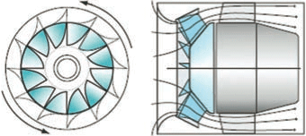
Figure 8: Mixed flow inline fan (Source: GPG383)
The installation of the fan
The efforts to provide an effective fan solution may be severely undermined by the relationship between the fan and the local ducted pathways for the air – this will be discussed in a future CPD article.
© Tim Dwyer 2011
For further reading in this area see:
- CIBSE Fan application guide (CIBSE TM42: 2006) – available for free access for CIBSE members through the CIBSE Knowledge Portal.
- ASHRAE HVAC Handbook 2008, Chapter 20. GPG383 Good Practice Guide: Energy savings in fans and fan systems – freely downloadable from www.carbontrust.co.uk
- For an excellent discussion of ‘stall’ see EUROVENT 1/11 Fans and System Stall: Problems and Solutions – free download www.eurovent-association.eu
References
- Murphy, J. ‘Selecting Efficient Fans’, ASHRAE Journal, April 2010.
- Carbon Trust CTV016 ‘Motor Drive Technology Overview’, Carbon Trust 2007.
- Coward, C. ‘Unhoused (Plug/Plenum) Fans: Is Their Performance Predictable?’, ASHRAE Journal, October 1997.