

There are many technologies contributing towards meeting the legislative requirements – and, more importantly, the environmental imperative – of lower carbon heat sources in commercial buildings. This CPD will consider some of the factors that are likely to influence the operational success when considering integrating condensing boilers with combined heat and power (CHP) and heat pumps.
The condensing boiler
A condensing boiler is equipped with sufficient heat exchange capability to reduce the flue gas temperature to below its dew-point temperature. By doing so, it is possible to recover a proportion of the available latent heat by condensing water vapour from the flue gas, which is a product of combustion.
Unless the condensing boiler is installed in such a way as to allow some of the superheated vapour in the flue gas to condense (as in the example shown in Figure 1), thus liberating energy, it will be lost to the atmosphere. The temperature of the water returning to a condensing boiler needs to be less than approximately 55°C so that the water vapour will condense – cooler temperatures will provide increased latent heat recovery, potentially adding 9% to the useful boiler output.
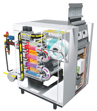
Figure 1: Commercial stainless steel condensing gas boiler. Yellow line shows gas path to meet combustion air, and then counter-flowing to the system return water that enters (shown as blue) at the base of the boiler, where the flue gases are coolest and where condensation takes place in the combustion gases that are leaving (Source: Elco)
The modulation of the output of a burner is important not only in terms of matching condensing boiler output to load – which, in turn, improves seasonal efficiency – but also because as burner output decreases, the efficiency of the heat exchanger increases, since the ratio of heat exchange area to input power increases. So at minimum burner input, losses are at their lowest and heat exchanger efficiency at its highest. This phenomenon means that modern condensing boilers are generally more efficient at their minimum output rather than at full output.
The combination of beneficial condensation and operating at partial load is illustrated in Figure 2. This shows the example performance (in net efficiency) of a condensing boiler with modulating output for different pairs of flow and return temperatures.
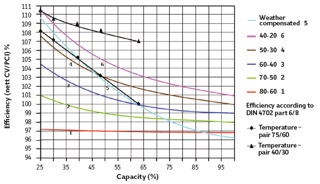
Figure 2: Comparative performance of modulating output for a condensing boiler at different flow and return temperatures (Source: Elco)
There are many heating systems – including individual buildings and ‘district’ schemes – operating at ‘traditional’ flow and return temperatures of 80°C and 60°C. Even when a ‘condensing’ boiler is operating at 80°C and 60°C return, its extended heat transfer surfaces mean it will still reduce the flue gas temperature (and so gain additional sensible heat), and so will always be more efficient than noncondensing boilers. However, compared with other temperature ranges, in this generalised example there are likely to be real benefits in operating efficiency at lower operating temperatures (as demonstrated in Table 1) and at part-load operation.
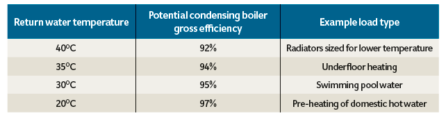
Table: Systems designed to operate at lower temperatures will enhance boiler efficiency
As long as the return temperature is below 55°C, at least some of the latent heat that would otherwise be lost will be recovered and, if the boilers are operating at part-load for a large proportion of the time, there is the greatest opportunity for best efficiency.
Gas-fired CHP or electrical heat pumps can be used in conjunction with condensing boilers as a means of providing a low-carbon and costefficient base load.
Gas-fired combined heat and power
Grid-supplied power delivers electricity to end-users with an overall primary energy efficiency of approximately 35% to 40%. A proportion of the loss – around 7% – is caused by the transmission losses though the electrical supply grid, but the remainder is down to the conversion efficiency at the power station.
The simplified example in Figure 3 indicates how localised generation through the use of combined heat and power can potentially provide a more effective use of primary energy. The benefit of CHP is highly dependent on the relative performance of the grid, the available fuel supply and the useful consumption of generated heat and electricity. Buildings that are suitable for CHP schemes are those where there is a consistent demand for heat – probably beyond that of a simple ‘9am-to-5pm’ office. CIBSE AM122 recommends that for successful CHP integration, the system should be designed to operate at maximum load in preference to boilers for the longest costeffective period.
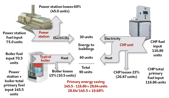
Figure 3: Simplified comparison of production of heat and electrical energy for use in buildings’ CHP compared with grid power and local boiler. Note: values used are variable, depending on location and application (Source: Elco)
Electrical and heating demand profiles for a simplified fictional building are shown in Figure 4. The diagrams include the output of a possible (and exaggerated) CHP solution – both heat and power output – of a spark-ignition gasengine powered CHP that typically produces about twice as much heat energy as electrical energy.
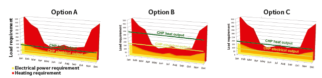
Figure 4: Example of building heat and electrical load profile with different CHP capacities
In this example, the heating demand fluctuates widely throughout the year, but the electrical demand stays reasonably constant and the summer base load is greater for the heating than the electrical demand. In ‘Option A’, the CHP will run continuously, thus ensuring a good payback for the machine. However, some electricity will need to be purchased, and a significant amount of heat is required from associated boilers. A larger unit would offset some of the carbon liabilities and provide a more cost effective solution, as electricity generated at source is more carbon efficient.
In ‘Option B’, the CHP unit selected is too large. Most of the heat demand is met, so the boilers will be smaller, and some electricity will be supplied back to the grid (sold at only 30-50% of the price of incoming electricity). But if the unit is run all year, there will be excessive heat rejection. The CHP could stand idle during the summer, but that is unlikely to be carbon or financially efficient. It could be linked with an absorption or adsorption chiller for summer cooling – known as ‘trigeneration’ – although without that facility, it is unlikely to qualify as ‘Good Quality CHP’ (as defined by the UK’s CHP Quality Assurance Programme3), as heat will be wasted.
In this case, ‘Option C’ provides a better balance. Some heat rejection in the summer may be permissible, as the advantages of meeting the electrical demand outweigh the implications of wasted heat. The installed boiler power is less than ‘Option A’. And, naturally, a different set of demand profiles will require specific analysis – 30 to 60-minute banded load data is considered appropriate to undertake such an exercise.
A concept example of CHP (with potential additional heat pump) integration is shown in Figure 5, as developed from CIBSE AM12. Integrating a thermal store enables the CHP to operate for longer and provides easier control.
However, an actual design will still necessarily have reasonably complex control requirements to ensure: minimum flow through boilers; back-end protection; opportunity for CHP ‘excess’ heat rejection; and, importantly, its most effective operation (the boilers would not be used to charge the store).
Heat pumps
The inclusion of a heat pump as an integrated element of the heat source for the main heating system is most effectively done if the recommendations of CIBSE AM12 are followed – designing systems with a return temperature of 40°C to allow application of renewable technologies. And just as with CHP, heat pumps are most appropriately designed as the lead heat source to maximise running time and potential savings in cost and energy. Heat pump performance will reduce as output temperature rises, as well as when the input temperature falls.
For typical electrically powered vapour compression (single stage) heat pumps, the thermodynamics restrict the economic upper limit of the working temperature to below 50-55°C. For higher temperatures that are used particularly for domestic hot water and traditional heating systems, a second heat source is required to raise the temperature to 60°C and beyond. So, if the heat pump heat source (for example, air or ground) is at a high enough temperature for effective operation, the heat pump will act as the lead-heating appliance and, if required, another heat source – such as boilers – are brought online to increase the temperature.
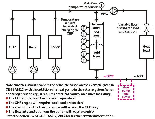
Figure 5: Schematic of example CHP in series with parallel boilers (based on CIBSE AM12, fig 9.4)
A heat pump could be integrated in a system as indicated in Figure 5, where it can act as the ‘lead’ heat source when effective to do so. This allows good year-round COP on heat pumps, together with suitable return temperatures to the boilers, allowing condensation of flue vapour.
Currently, finding both CHP and heat pumps on the same system would be unlikely, as they have similar requirements for success: to operate for long periods, and to act as a base load machine. Capital investment for both is more expensive per kW of delivered heat than with condensing gas boilers.
UK government incentives for assured quality installations
- CHP can attract Climate Change Levy exemption that can reduce the ROI period by one to two years
- Enhanced Capital Allowances for both CHP and heat pumps can save 7-8% of the capital cost over the plant lifetime (and can include auxiliary heating equipment)
- Renewable heat incentive available for metered heat pump heat
- Business rating exemption applies to CHP and associated plant
Combining the technologies
When different heat sources are combined in one system there are considerations of flow dynamics, operational safety and temperature control. These are covered in CIBSE AM12 and in greater depth in CIBSE AM15.6
As the UK power distribution grid is ‘decarbonised’ – so improving heat pump viability – there may be more opportunity to benefit from an arrangement as shown in concept in Figure 5. The heat pump and CHP unit are not competing for the base load but both are contributing towards it. In low load conditions where the heat pump and CHP need to be supplemented by the boilers, the boilers may still operate in condensing mode, and will likely operate at part load.
This system also ensures that the heat pump and CHP will always run to their maximum potential.
However, regardless of whether the hot water is provided by a continuous flow water heater, in larger systems – where there is a need for recirculation pipework (as illustrated in Figure 5) – there is inherently increased system water volume and opportunities for ‘dead-legs’. When taps or shower-heads stop running, after use, the final branch pipework will be full of cooling water capable of breeding legionella bacteria, so appropriate safeguards must be put in place – such as self-draining shower heads.
© Tim Dwyer, 2015.
With thanks to Mark Ferris of Elco, who has provided the practical applications used in this article.
References
- Conversion factors – Energy and carbon conversions – 2013 update, www.carbontrust.com/media/18223/ctl153_conversion_factors.pdf
- CIBSE AM12 Combined Heat and Power for Buildings, CIBSE 2013.
- www.gov.uk/combined-heat-power-quality-assurance-programme
- www.gov.uk/combined-heat-and-power-incentives
- www.gov.uk/government/publications/use-ofchpqa-to-obtain-enhanced-capital-allowances
- CIBSE AM15, Biomass heating, CIBSE 2014.