

The recent publication of the draft Heat Networks: Code of Practice for the UK, by CIBSE and the Combined Heat and Power Association (CHPA), has highlighted that the proper application of heat networks requires a thoroughly considered approach, to ensure that the installation will properly meet a real need, rather than provide a token ‘greenwash’ to a project.
Referring to the recent draft code of practice (CoP), this CPD will draw on the experience of a major supplier of systems for heat networks – particularly for multi-tenanted residential applications – to consider the application of condensing boilers, alongside solar thermal and gas absorption heat pumps (GAHP), as a means of providing a source of heat that is not only effective, but also carbon efficient.
Heat networks can provide an attractive solution for residential landlords. They remove gas appliances from dwellings, improving safety and removing gas systems that would otherwise require annual inspection. The simpler maintenance requirements – particularly of the ‘heat interface units’ that replace individual boilers – mean that the need to access tenants’ properties is reduced. Such networks allow pre-payment for energy, and will often include home energy displays that help tenants visualise and regulate their energy use. Experience has even indicated that some landlords are using these systems to check on vulnerable tenants, enabling them to determine when there is no metered energy use. The overall energy savings from heat networks allow the incorporation of renewable heat sources on a larger scale than would be practical on individual properties, helping landlords meet their obligations and providing opportunities to help tackle fuel poverty.
The path to successful integration of a heat network, whether serving a single building with multiple tenants or spanning a larger site or conurbation, is mapped out in some detail in the draft Heat Networks CoP1 – the proposed developmental stages are abstracted from that document and shown in Figure 1.
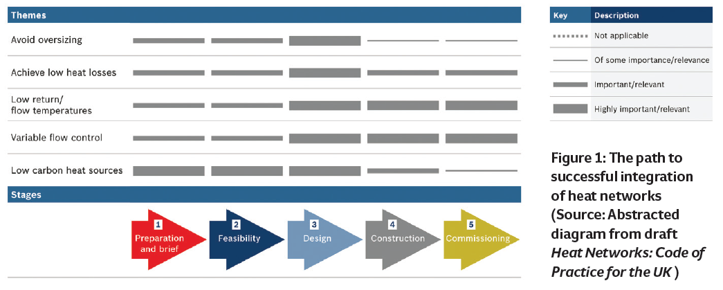
Figure 1: The path to successful integration of heat networks (Source: Abstracted diagram from draft Heat Networks: Code of Practice for the UK )
To ensure the greatest opportunity for operational savings (and success) avoid oversizing, both in the heat network and final heating systems. This will ensure a thoughtful, well-informed calculation and design process, using good-quality data to predict reliably or – better still – apply measured local records to determine the system demands. This will also deliver a system that is more controllable, and will require less maintenance than one that is oversized. If a heat network is being added as part of a refurbishment project, the thermal elements of the building are likely to be improved, so reducing the loads and consequent system demand from those historically recorded.This necessitates calculation/modelling based on the realistically deliverable improved thermal properties. Where the existing heating system has been designed for the conventional 82°C flow and 71°C return, it is usually possible – with appropriate variable volume control – to reduce the flow rates to provide 80°C/60°C radiator circuit temperatures, resulting in only a small loss of output, typically about 12.5% for these temperatures.1
For a new construction, low flow and return temperatures are the default option. This will allow heat sources, such as heat pumps, and CHP with condensing heat exchangers – as would be used where combined heat and power provides the heat source – to work at higher efficiencies. However, if there were a specific available source of higher-temperature heat – that is, higher exergy – it would be appropriate to consider the benefits of reduced flow rates resulting from the availability of a higher flow/return temperature difference.
The relationship between the flow temperature, the heat interface unit (HIU) and type of heat emitter is key during design. The secondary systems accessing the distributed heat through HIU, as in Figure 2, will determine the minimum flow water temperature in the mains network. In smaller systems – with losses less than 10% in the main network – a flow temperature approaching 65°C to 60°C is used as a starting point in establishing suitable operational conditions. A HIU is selected that can give the desired domestic hot water (DHW) flow rate at the outlets – the plate heat exchanger within the HIU and the primary flow temperature will dictate the flow rate from the taps. If the DHW load can be successfully supplied in a domestic installation, it is likely that the HIUs would be able to meet the heating load. The type of heating employed by individual consumers will also influence the flow temperature – in most cases, flow temperatures should be the minimum required to meet the demand, and the flow/ return temperature difference maximised. The heat emitters are selected taking into account the lower mean temperature and installation practicalities. Despite the benefits of operating at low flow water temperatures, underfloor heating might not always be physically practical or cost effective in a particular application. Radiator systems may need to be larger to give the same output as at the traditional flow/return temperatures of 82°C/71°C at the reduced flow temperatures.
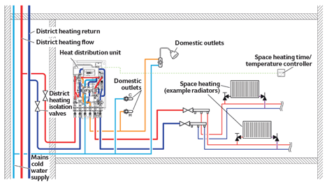
Figure 2: Example of distribution of heat to individual consumer from heat network (Source: Based on Bosch Commercial and Industrial Heating illustration)
In practice – and particularly for smaller networks – the temperature difference will vary greatly. When there is a DHW demand from an individual HIU, the return may be as low as 20°C, but during heating it will be higher – for a radiator heating system it will typically be around 50°C. Some HIUs can optimise the return temperature from the heating by varying the flow rate. Employing variable flow systems to deliver the heat to the final load provides the opportunity for variable speed pumping – and resultant pump energy savings – as well as ensuring that a high temperature difference is maintained between the flow and return water. This will ensure that the maximum practical potential heat is extracted from the primary heat network – so maintaining low return water temperatures – plus better efficiency from boilers and renewable heat sources, as well as reduced system losses. Where a heat network is retrofitted to a building with existing heating systems (the HIU ‘substituted’ for an individual boiler), experience has shown that the flow/return temperature difference can vary from about 7K to 30K, depending on the type of load at the time.
The application of a low-carbon heat source is, of course, fundamental to planning the route towards a low-carbon solution. If, for example, there was the available resource of so-called ‘waste’ heat – with appropriate exergy –from a local power plant, industrial process or geothermal source, then this is likely to shape the brief for any subsequent heat network. In reality, however, such accessible heat is a rare commodity, so opportunities for alternative ‘low carbon’ sources can be employed, often in combination with fossil-fuelled technology – so-called ‘bimodal’ systems. Solar thermal panels and gas-fired air sourced heat pumps are two frequently used low-carbon heat sources.
These are typically arranged using two buffer vessels, one dedicated to the renewable heat source, with a bypass arrangement, and the other used as the main buffer for the heat network. This is shown as a simplified schematic for a gas-fired condensing boiler and solar thermal panel heat source in Figure 3. The solar thermal panels will charge the solar thermal buffer tank when the solar irradiance is sufficient to increase the temperature of the water in the buffer tank (up to a safety maximum). The return water from the network draws water through the buffer when it is advantageous to do so – that is, when the temperature in the top of the buffer is, typically, 5K warmer than the return temperature from the heat network. The buffer temperature will reduce until it is less than the return, and the buffer will then be bypassed by the heat network return. This cycle will repeat, depending on the availability of the solar resource.
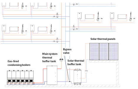
Figure 3: Example simplified schematic of a heat network with gas-fired condensing boilers and solar thermal panels heat source (Source: Bosch Commercial and Industrial Heating illustration)
The solar thermal buffer vessel will typically be a coil heat exchanger, as this is suited to keeping the glycol-filled solar circuit separated from the network water within the buffer. To establish a suitable buffer size, simulation software – such as the commercial T*Sol or freely available RETScreen – may be used to explore the benefits of different buffer sizes. For example, this might examine the benefits of larger storage against physical constraints and capital investment.
A GAHP-led system is shown in Figure 4. The heat pump acts as the lead heat source, with top-up from the boilers as necessary. The gas-fired air-sourced heat pump will feed into the GAHP buffer tank, and will be sequenced by the controller based on the temperature within the GAHP buffer (using multiple temperature sensors in the buffer).
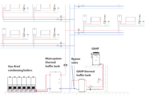
Figure 4: Example simplified schematic of a heat network with gas-fired condensing boilers and gas-fired air-sourced heat pump (Source: Bosch Commercial and Industrial Heating illustration)
As soon as the temperature at the top of the buffer is higher than the return from the system, the bypass will activate, sending the flow through the GAHP buffer. A greater output from the GAHP will ensure that the proportion of heat supplied by the gas-fired condensing boilers will be reduced.
When selecting the required capacity of the GAHP, it is necessary to consider carefully both the base load, and the peak load, while also considering what level of capital investment is appropriate.
The capital cost of the gas-fired air-sourced heat pump will be greater per kW than a condensing gas boiler, so to deliver a return on investment (ROI), the heat pump should operate at full load for the maximum number of hours per year. For example, it would make little financial sense to size the GAHP to meet the peak load that might only be experienced a few days in a year. It is better for the GAHP to be sized to meet the bulk of the load – perhaps up to 60% – to ensure that payback times are realistically feasible. This, of course, may be modelled.
Buffer sizing for GAHP has some ‘rules of thumb’ – for example, 300 litres per GAHP unit – and so is relatively straightforward, but any reputable manufacturer will be able to provide extensive advice on application.
The main buffer vessel on the heat network is there to provide storage capacity for peaks of demand. The main buffer vessel will even out transient demand on the heat sources, allowing boilers to come into operation and get up to temperature. This also ensures there is no noticeable change in the delivered performance to the end user – the DHW will be particularly sensitive to the availability of network heat, whereas heating is less demanding, since the thermal inertia of the building and the heating systems will mean that small dips in performance could go unnoticed. The main buffer vessels are typically sized to give 10 minutes of peak diversified demand capacity.
Control modules to ensure effective operation are available as part of a manufacturer’s integrated bimodal solutions, so maximising the proportion of lower-carbon heat.
Both in new and refurbishment projects, pre-fabrication delivers the advantage of keeping all the main fabrication – including ‘hot works’ – away from site. This gives benefits in cost, tenant disruption, and health and safety. It avoids many access issues in existing boiler rooms and can mean that plant is tested before arrival on site. An example prefabricated plantroom will contain boilers, buffer, pumps, expansion vessels and controls. It would be craned into position with loading hooks, to deliver a system such as the example in Figure 5.
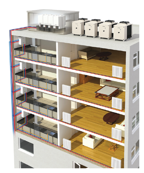
Figure 5: Application of heat network with integrated gas-fired condensing boilers and GAHP (Source: Bosch Commercial and Industrial Heating illustration)
More detailed design for heat networks is discussed extensively in the freely available CIBSE/CHPA publication draft Heat Networks: Code of Practice for the UK, and in the recently published BRE document A technical guide to district heating, where wider applications of networks are discussed – much of which is relevant to the heat networks in multi-tenanted buildings.
© Tim Dwyer, 2014.
References
- Draft Heat Networks: Code of Practice for the UK, CIBSE/CHPA, 2014