

As the technology further matures, variable refrigerant volume (VRV) or variable refrigerant flow (VRF) systems are being applied to a wider range of HVAC services. Although originally designed to provide comfort air conditioning through air-to-air heat pump heating and cooling, they have evolved to encompass heat recovery systems, small (or mini) VRV systems, as well as extensive systems that can function effectively at more extreme ambient conditions – so that VRV can be used in countries with cooler and warmer climates.
This CPD will consider the application of advanced VRV systems that can provide energy and cost-effective domestic hot water, as well as fulfilling their role in comfort conditioning.
VRV systems can now provide heating and cooling to other building services, beyond the demands of direct comfort conditioning requirements. The heat pump ‘split system’, designed for heating water, was originally developed in the 1980s. By using the hot gas refrigerant (leaving the compressor), passing heat through a plate heat exchanger to a cold water supply, it was possible to heat water more effectively than using direct electrical immersion systems. However, due to the low cost of natural gas and low demand for energy- efficient products during that era, this type of heat pump hot water production system was not widely adopted, and manufacturing development was held back until demand increased.
As technology evolved and the focus on energy efficiency grew sharper, it became appropriate to re-introduce this technology – but not only as a split system (single indoor unit to single outdoor unit combination), but also on distributed VRV systems. Concurrently, manufacturers were also introducing direct refrigerant connections to coils in air handling units, as a means of heating and cooling ventilation air, using the refrigerant as the working fluid.
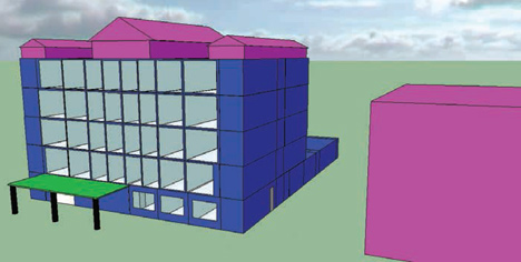
Figure 1: Thermal modelling of hotel
Subsequently, there have been many projects that utilise VRV systems that can control the temperature in ventilation air supplies and hot water systems. However, the success of such integrated systems requires an holistic appreciation of the building and its environment, the system (and its capabilities and practical limitations) and the operational realities. Manufacturers have the ability – and the required components – to meet the opportunities offered by VRV-linked direct refrigerant heat transfer within AHUs and plate heat exchangers, but each application needs to be carefully considered to ascertain the best system selection. Some air-handling applications lend themselves to connection to heat pump systems that are dedicated to looking after the fresh air requirements, whereas other applications can provide efficient hot water production and, concurrently, provide the space-conditioning requirement by utilising heat recovery technology.
Modelling advanced VRV application to supply ‘high temperature’ domestic hot water for an example hotel
A good potential application of using a VRV-linked system to provide domestic hot water with high efficiency is in hotels. A thermal model was created to explore a hotel’s cooling and domestic hot water requirement to establish what could be reasonably, and effectively, produced by a VRV system. The hotel was based on standard 2002 regulation UK constructions, with facilities on the ground floor for a lobby area, gym, meeting rooms, office, restaurant and kitchen with the four floors of guest rooms above. For this modelling exercise, it was located in Strasbourg, France, a region that has a climate slightly more extreme (both in summer and winter) than London.
The building was analysed using IES VE software in conjunction with a ‘plug-in’ designed specifically to model the operation of Daikin VRV systems. The model had each space analysed in detail to identify the best possible performance for a heat recovery system. This was a lengthy process, and was undertaken to evaluate the opportunities for the technology, going beyond the requirements of a ‘normal’ design process. (This in-depth analysis is not yet available commercially.)
The overall (seasonal) performance of a VRV-based system is operationally determined by the heat removed (as cooling) from the building, combined with that produced by the compression cycle being matched by a heating demand. The building’s north- facing guest rooms and the lobby area (with constantly opening and closing doors) provided a heat demand, particularly in the mornings, although the majority of the building’s air load was for cooling – some areas having significant heat gains, such as the restaurant, meeting rooms and south-facing guest rooms.The internal space and fabric loads were combined with the domestic hot water requirements to provide an annual heating energy requirement of 1,233 MWh and an annual cooling energy requirement of 922 MWh.
This indicated that there was opportunity to transfer available heat usefully around the building. However, the key – and more challenging – task was to provide a realistic and detailed simulation of building operation so that simultaneous heating and cooling loads could be matched to investigate the potential for heat recovery. Heating the domestic hot water can provide an efficient means of matching the cooling for very little additional energy.
For example, in Figure 2, for a particular week in April there is on average around 80 kW of continuous free capacity available and, at some points, as much as 220 kW of capacity that can be recycled for use elsewhere in the building.
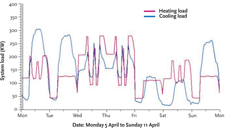
Figure 2: Hotel heating and cooling demands over a week in April
A ‘traditional’ VRV-based system might well operate with a heat pump VRV system for air temperature control, and a natural gas supply providing the heat required to satisfy the hot water demand.
A development of this system would be to use a (low temperature) VRV hot water system that uses the heat rejected from the building and compressor to raise the domestic water temperature. Practically, this can raise the water up to a maximum of 55°C, and so this system typically requires additional gas or electric ‘top-up’ heating to maintain safe temperatures for Legionella control. That type of system was not considered in the comparison modelled in this example.
The more advanced application is a VRV heat recovery system utilising high temperature domestic hot water production via a ‘cascade’ hot water exchanger. A cascade system uses two vapour compression cycles as shown in Figure 3. A R410a refrigerant circuit has an evaporator in the outdoor unit of the VRV system (section 1), drawing heat from that rejected by the VRV cycle. The compressor increases pressure and temperature, and the refrigerant subsequently flows to the hot water production unit (section 2). The R410a is condensed, exchanging heat with the evaporator of an R134a refrigerant evaporator. Again, using vapour compression, the temperature of the R134a is increased to (potentially) 80°C, feeding the condenser heat exchanger (section 3) to provide hot water.
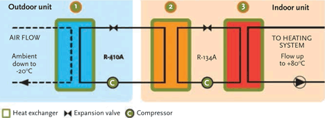
Figure 3: Cascade refrigeration to effectively produce hot water from heat rejected by VRV system
For this example model, the system was set to supply heat to provide a hot water flow temperature of 60°C.
The results of the analysis comparing the two types of system, as shown in Figure 4, demonstrate some notable differences. Over the year, the VRV/natural gas system provides a VRV coefficient of performance (COP) of 6, combined with a natural gas heating system effectiveness of 0.9, compared to the VRV/ cascade system COP of 6.9. In the cascade system, the modelled VRV yearly output increases to 1,867 MWh (from 906 MWh) because it is providing the heating source for the hot water.
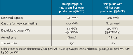
Figure 4: Modelled annual carbon emissions and energy costs
With the more advanced heat recovery systems, there are opportunities to readily employ – at very low additional cost – heating or cooling that would otherwise be rejected. At such times, this can allow the environmental conditions to be more closely controlled to design conditions, at marginal additional cost, potentially improving comfort and occupier satisfaction. The small increase in delivered capacity in Figure 4 is due to the model providing such a benefit.
The analysis shows a significant difference between the two systems. The selected system is based on a ‘design’ heating condition. However, in reality, this may be exceeded, so the heating performance of the system should also be analysed at extreme winter conditions. Heat pumps are very efficient at producing domestic hot water, but in the case of a hotel, the comfort of guests is a prime requirement and priority. Further simulations at an extreme winter conditions are likely to indicate that that there could be a shortfall in heating capacity. One solution could be to increase the capacity of the heat pump system, but by increasing the peak capacity of the system it is likely to reduce the year-round efficiency of the system.
Figure 5 indicates the general relative performance of a VRV system. The optimum performance is between 50-70% capacity and, typically, this is where a properly-sized system will operate most frequently. However, if an ‘oversized’ system is used (to satisfy extreme heating equirements), it will spend the majority of operational time at a lower capacity and, therefore, at lower efficiency.
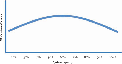
Figure 5: Approximate variation in VRV system efficiency at different loadings
In the example, rather than increasing the system maximum capacity to accommodate infrequent high heating loads, it is likely to be more effective to use a bivalent system, with a boiler that is used when high hot water loads and, typically, low outdoor temperatures coincide.
Integrating AHU cooling and heating coils
Traditional methods of cooling and heating the supply air (using separate chillers and boilers, and water-based coils) may be replaced by dedicated VRV system connected coils (carrying ‘refrigerant’) within the air handling unit (AHU). This can eliminate a stage of heat exchange by feeding AHU cooling and heating coils directly with refrigerant, so increasing efficiency. The selection of a VRV system for cooling the supply air relies primarily on the load, but it is important that this load is defined correctly, based on the required on and off coil conditions.
A VRV system can also be provide the source of heat for the AHU heating coil. VRV systems are primarily designed for indoor coils – rather than those in an AHU – and so it is particularly important to check the operational range with the manufacturer to ensure that it can meet the design load. Some manufacturers do not recommend using the coils to heat low temperature air (below 10°C) – this will be dependent on the system supplier.
Using VRV equipment as the direct heating/cooling source can provide an efficient application in itself. However, by considering the heating and cooling coils of the AHU systems in conjunction with the coils in the room units can significantly increase the opportunities for heat recovery, as previously waste heat and cooling can be reused elsewhere in the building systems, as shown in Figure 6.
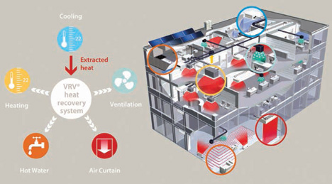
Figure 6: Elements of the building services system recover otherwise wasted heat through the VRV system
With careful analysis and design, VRV systems can be very effective and efficient at providing air and water temperature control in buildings. As designs become more ambitious in integrating formerly disparate systems, there is a need for more careful analysis and modelling that will rely on closer working relationships between manufacturer, designer and operator to ensure that systems provide seasonal efficiencies that meet expectations.
© Tim Dwyer and Richard Green, 2014.