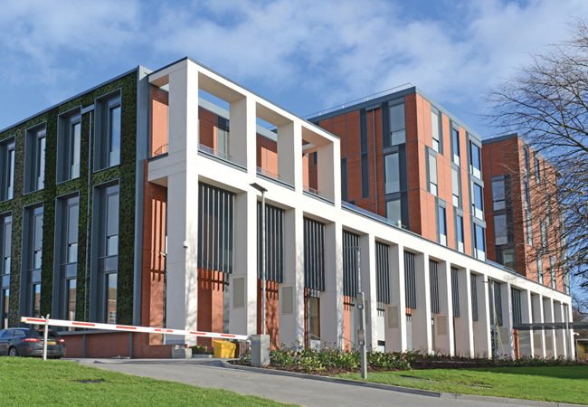
If degree certificates were awarded for outstanding building performance, then the University of Leicester’s Centre for Medicine would have graduated with first class honours. The new £42m building, which opened to students in February, includes a 1.6km-long ground-to-air heat exchanger, inter-slab cooling and a highly insulated and airtight building envelope. It also has the kudos of being the UK’s largest Passivhaus-certified building.
The university commissioned the building to enable it to bring together the schools of medicine, health sciences and psychology under a single roof. It also wanted its new building to have very low carbon emissions to help the university achieve its ambition to be recognised for ‘environmental and sustainability excellence’.
Project team
Client: University of Leicester
Architect: Associated Architects
Building services engineer: Couch Perry Wilkes
Airtightness consultancy: HRS Services
Passivhaus consultant: WARM
Structural engineer: Ramboll
Accordingly, the university set its design team of engineer Couch Perry Wilkes and Associated Architects the challenge of designing a building that was inherently low energy in use to achieve an A-rated EPC and, perhaps more demanding, an A-rated DEC.
The team’s response has been to design a 13,000m2 building that is Passivhaus-certified. The scheme comprises a two-storey podium structure, which houses the main teaching spaces, both a 300-seat and smaller 150-seat lecture theatre, and informal learning spaces.
Three linked towers rise up from this podium; these contain a mixture of research laboratories, teaching spaces and cellular offices. Impressively, the scheme has an annual space heating demand of just 15kWh.m-2 and a total annual primary energy use of 116kWh.m-2 as defined by Passivhaus Planning Package (PHPP) – quite an achievement for a large academic building with variable occupancy that accommodates up to 2,000 students and 400 staff.
The PHPP spreadsheet was key to the scheme achieving Passivhaus certification. The tool proved invaluable in exploring alternative design solutions and enabling the design team to assess the outcomes of enhancing the performance of some construction elements. It could then offset this against less well-performing elements, to arrive at a design that optimised both performance and cost. In fact, one of the benefits of using Passivhaus on a large project such as this is that it increases the number of opportunities for construction variations, when compared to a small-scale Passivhaus scheme.
According to Stephen Ball, a director of Couch Perry Wilkes, the fundamentals of construction are not significantly different for a Passivhaus building of this scale when compared to any other Building Regulation compliant building; the key is in the detailing. ‘We know that if we put in the correct amount of insulation to meet the Passivhaus U values, we’ll limit the building’s heat losses. It is the detailing to limit thermal bridges, and to maintain an airtight barrier within the building fabric, that are critical to achieving Passivhaus energy targets,’ he explains.
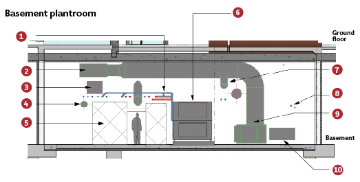
Key
1 LPHW and CHW pipes serving heating and cooling coils within AHU
2 Intake bypass duct at high level within plantroom
3 Return air ductwork runs to riser
4 Dirty extract duct from high level fan runs to join exhaust
5 Air handling unit access and plantroom walkway
6 Air handling unit No. 1 (west block – ground and first)
7 Supply and extract ducts run beneath GAHE intake bypass duct
8 Underfloor heating/cooling pipework
9 GAHE intake bypass joins low-level intake duct
10 Main intake duct runs at low level within plantroom
Preventing uncontrolled ventilation is one of the fundamentals of Passivhaus design. It was so critical to this scheme that Couch Perry Wilkes employed consultants HRS Services to peer-review the building fabric airtightness details and to pass comment on their effectiveness early in the design development. ‘We were employing a second consultant to have an eyeball at what the architect had done to see if it was buildable to the Passivhaus regime,’ says Ball.
Getting a contractor on board early in the design development was also fundamental to developing a buildable solution. The project, which was tendered as a two-stage design and build contract, was won by contractor Willmott Dixon working with low-energy building specialists and Passivhaus certification organisation Warm.
Willmott Dixon chose to construct the two-storey-high walls of the podium structure in line with the design team’s original proposal. This was based on traditional masonry wall construction, complete with low conductivity wall ties and a 300mm cavity fully filled with insulation. Inside, the internal blockwork has been finished with a wet-applied plaster to provide an airtight solution. Between the masonry elements are infill sections of Passivhaus-certified curtain wall; these are sealed to the wall using specialist tapes and membranes to prevent any air leakage.
On the upper floors Willmott Dixon opted to swap the design team’s proposed cladding solution of precast concrete sandwich panels for a curtain wall solution incorporating brick slip panels. This was because the contractor had concerns that construction tolerances – and the need for movement joints – would have made it too difficult to achieve the required fabric airtightness. This solution also, conveniently, put the entire curtain walling system and responsibility for its airtightness and thermal performance, into a single subcontractor façade package. ‘Willmott Dixon came up with a different cladding solution that allowed them to maintain the airtight line and improve buildability,’ says Ball.
The change in façade construction was not without its complications; while the curtain wall solution was extremely airtight, it also required the addition of insulation internally to enable it to achieve a façade U-value of 0.13W.m-2.K-2 required by the Passivhaus Institute. Adding insulation internally, however, increased the risk of interstitial condensation, which meant additional seals and vapour control layers had to be incorporated.
The solution was clearly successful – when the building was pressure tested its pressure loss was 1m3.m-2.h-1 at 50Pa, well within the Passivhaus target. In addition, heavyweight internal partitions were added to the corridors to compensate for the lack of thermal mass in this solution.
With the fabric air losses minimised, fresh air is delivered to the building in a controlled manner using mechanical ventilation with heat recovery. Passivhaus places as much emphasis on ventilation and avoiding overheating during the summer as it does on keeping a space warm with minimal heating during the winter. Accordingly, the scheme includes a total of 10 air handling units (AHUs): five in the basement plant room, two in each of the two plantrooms situated on top of the towers, and one – supplying the main 300-seat lecture theatre – located in a dedicated plantroom beneath its raked seating.
All of the AHUs incorporate a thermal wheel to recover heat from the air before it is exhausted. In addition, the AHUs located in the basement serving the densely occupied teaching and lecture theatres, contain cooling coils to lop peak temperature during warmer periods.
Passivhaus places as much emphasis on ventilation and avoiding overheating during the summer as it does on keeping a space warm with minimal heating during the winter
To help reduce the primary energy demand by tempering the temperature of the incoming fresh air, the scheme incorporates a sinuous pipe labyrinth buried beneath the building and connected to the basement plantroom. This is arranged in what Ball calls a ‘Tichelmann style’ with large inlet and supply headers connected by rows of much smaller, 0.25m diameter, interconnecting heat transfer pipes. Air enters the labyrinth through air intakes concealed in colonnade lining the plinth façade. Silver particles incorporated into the heat exchanger’s lining help inhibit bacterial growth.
The ground-to-air heat exchanger (GAHE) tempers all of the fresh air supply to the basement AHUs by pre-cooling it in summer and preheating it in winter. This fresh air supply of 34,200m-3·h-1 represents approximately 30% of the total fresh air entering the building. ‘There is a significant amount of earth tube; even though it is not a prerequisite of Passivhaus, it makes sense to get the benefits of heating and cooling from the earth because the building is going to have mechanical ventilation throughout the year,’ Ball explains.
Providing technical assurances of the energy savings expected to be delivered by the GAHE system to the Passivhaus institute proved to be quite a challenge, although once the occupancy profiles had been refined so that the demand for mechanical ventilation was known, the benefits became clear.
Equally challenging was weaving the heat exchanger ducting between the building’s piles, drainage pipework and the tower crane bases. The size of the building, and the subsequent volume of air that had to be delivered to ventilate it by the AHUs, was so high that there were limited options for Passivhaus-certified air handling units, and none available that had demand-driven controls.
Shining a light
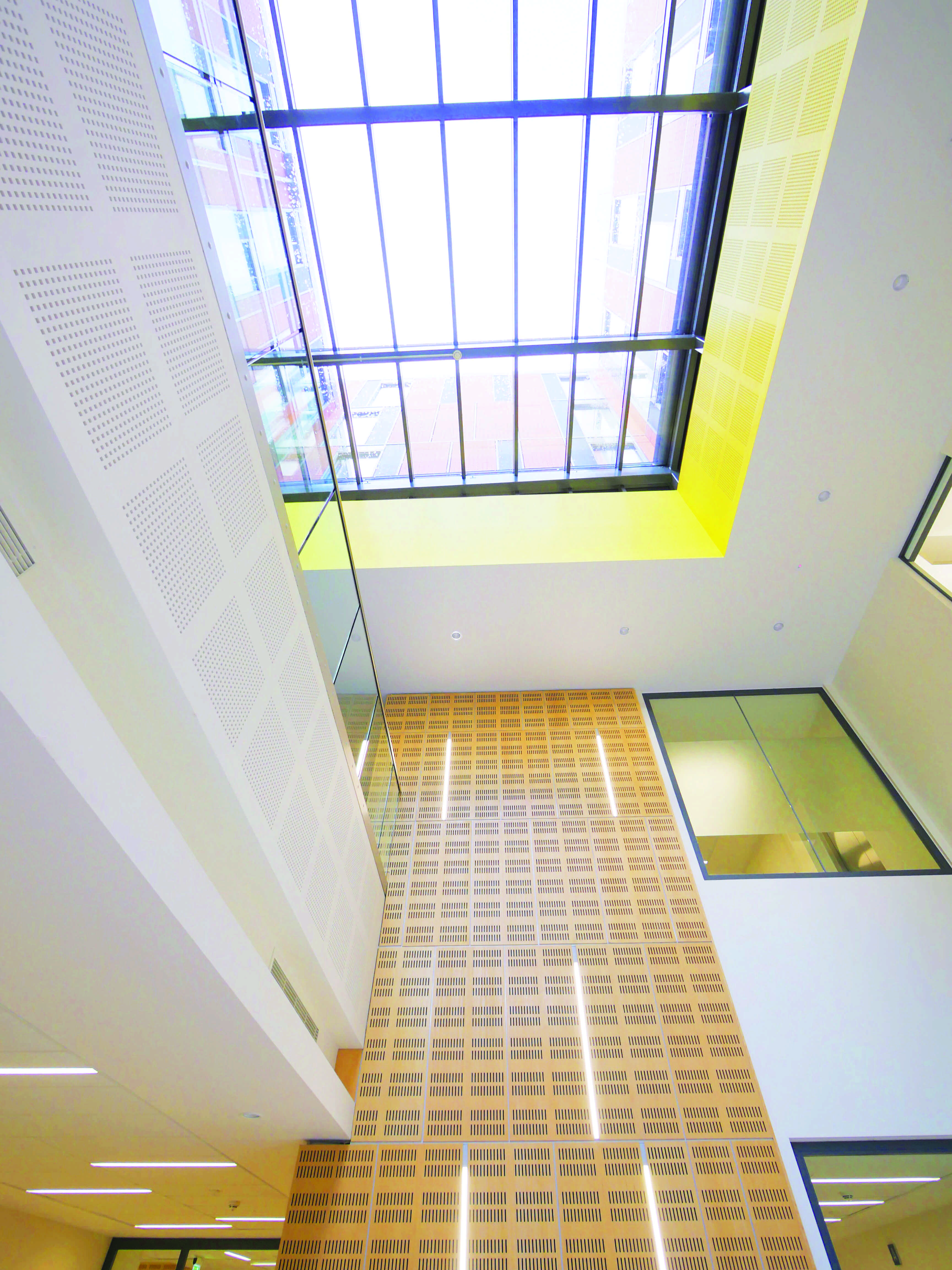
Couch Perry Wilkes also spent time developing a design that would maximise the amount of daylight entering the building to minimise the need for artificial light. ‘Lighting tends to take a bit of a back seat with Passivhaus, which is more about heating and airtightness,’ Ball says.
The consultant was helped in its endeavour by the narrow floorplates on the towers’ upper levels and the full-height glazing, which allows daylight deep into the floorplates. ‘All lighting is daylight-dimmed so that we have just the right amount of light in the rooms, which has a massive impact on primary energy demand.’
The scheme also includes Passivhaus-certified rooflights set into the roof of the plinth structure, to allow daylight into these deep plan spaces. ‘We’ve used our lighting designers to develop a solution that goes way beyond what Passivhaus requires,’ says Ball.
‘We were operating right on the margins of passing PHPP, so bespoke units had to be made, tested by BSRIA and clad in insulation to make them more efficient,’ Ball says. Even so, because the units were without a Passivhaus certificate, the manufacturer’s claimed efficiency had to be reduced by 12%. ‘The AHUs are not Passivhaus certified so we had to take a hit under PHPP’.
Fresh air is delivered to the occupied zone via raised access floors with supply
air displacement grilles throughout. Corridors and atria are utilised as the return air path for adjacent mechanically ventilated areas to improve the air quality in these transient spaces.
What Ball terms ‘solar reservoirs’ are located at the top of each atrium, where the heat energy will accumulate during the winter. This energy is extracted from the reservoir and transferred to incoming fresh air via heat exchangers in the AHUs.
During design development, the layout of the AHUs within the plantrooms was amended to minimise the lengths of the exhaust and intake duct runs, and to ensure all supply air distribution ductwork was contained within the envelope to reduce heat losses from the ductwork. It was also found to be beneficial to bring the rooftop plantrooms within the Passivhaus envelope to help limit the number of fabric thermal bridges and to improve their buildability.
Keeping cool
The building’s high occupancy levels meant that limiting the internal temperature in the summer was one of the biggest design challenges. ‘Because it is an airtight building, one of the issues with the scheme was getting rid of the heat in summer,’ says Ball.
A three-pronged approach is used to tackle heat gains: firstly the thermal mass of the building’s concrete frame and the underside of the floor slabs are exposed internally to help limit temperature fluctuations within the building; secondly, the heat absorbed by the thermal mass is removed at night by running the AHUs to recharge the thermal mass; and finally, the concrete soffits above the heavily occupied areas on the ground and first floors are cooled using a labyrinth of 7km of cooling pipework embedded in the slabs. The pipework is fed by chilled water from roof-mounted air-cooled chillers.
The chillers are connected to large chilled water buffer vessels located in the basement close to the cooling coils to reduce pump power. The buffer vessels are sized to maximise the benefits of the ‘free cooling cycle’ of the chiller plant. The vessels are charged and the system served (simultaneously) for the majority of the time entirely by the free cooling equipment without activating the chiller compressors. Annual space cooling energy demand is 1kWh.m-2.
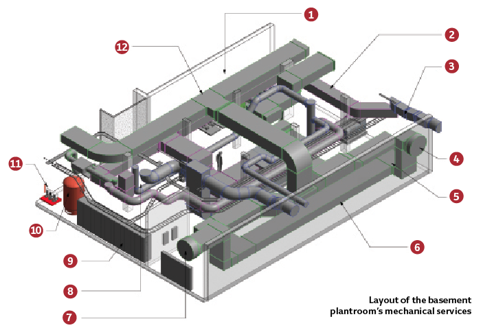
Key
1 Various plant sits against back wall within plantroom
2 Return air ductwork
3 Supply ductwork
4 Fresh air via GAHE intake ductwork enters plantroom and drops to low level
5 Concrete enclosures housing ductwork
6 Intake ductwork at low level
7 Fresh air via GAHE ductwork enters plantroom at high level
8 Supply and return ducts rise to above
9 LV switch panel
10 CHW buffer vessel
11 CHW pressurisation set
12 GAHE intake bypass ductwork
On the upper floors solar gains are controlled using mechanically operated roller-shutter type external blinds under control of the BMS. Fortunately the building’s facades have proportionately less glazing than would be the case for a Passivhaus home. ‘We’ve got about 33% glazing on the south (as opposed to 40-50% for a Passivhaus home) because we don’t need the solar gain with all of the heat gains from people and equipment; the windows were mostly there for daylighting’ says Ball. Even so, the blinds are necessary because the university has taken an egalitarian approach to staff accommodation by requiring each office to have an equally sized floor-to-ceiling triple-glazed window, regardless of orientation.
The blinds form part of, and are integrated into, the building’s Schüco curtain wall system. They are constructed from narrow aluminium louvre blades, which provide shading while still allowing external views.
Occupants also have the option of ventilating their rooms naturally in spring and on cool summer days. The triple-glazed windows do not open, but adjacent to the glazing is an opaque panel, which can be swung manually to reveal a louvred opening that will allow fresh air to enter the spaces.
‘In winter the building is completely sealed and mechanically ventilated, but in the intermediate period occupants can open these panels like in any other naturally ventilated building,’ explains Ball. When the room is being naturally ventilated, the BMS will turn off the mechanical ventilation.
We were employing a second consultant to have an eyeball at what the architect had done to see if it was buildable to the Passivhaus regime
– Stephen Ball
Similarly, the BMS will also turn off the small radiator included in many of the rooms. The radiators have been included to enable the building to cope with extremes of occupancy during the winter. ‘Because this is a building that may, or may not, have staff or students in certain rooms for long periods of time, there is no point in having a heating system that heats every space to the same temperature,’ Ball explains.
He says the radiators have been sized ‘just to take the edge off the room temperature’. The scheme also includes underfloor heating on the ground floor. Annual space heating demand is 15kWh/m2. All space heating demand is supplied to the building from Leicester’s district heating system.
The scheme also includes 115m2 of solar PV in response to the need to achieve an EPC A-rating and meet the requirements of Leicester City Council’s local plan.
The building was occupied in February. One of the biggest challenges with the move was in limiting the legacy IT equipment occupants could bring into the building, because it all has to be included in the building’s Passivhaus primary energy consumption figure. It was a process made all the more complicated by the amalgamation of three departments, with three different ways of doing things, all of which had to be consolidated into a single solution.
‘We had to take a long run-up to explain to people that they would not be able to bring all of their old equipment with them – we started the process several years in advance,’ explains Ball. The process must have been successful because annual primary energy consumption has been calculated at 116kWh.m-2, just under the 120kWh.m-2 maximum permitted by Passivhaus Institute.
‘This is another leap forward for Passivhaus in the UK; if you want to go down the Passivhaus route you have to start the design process really early on – which means designing a buildable, insulated airtight building and deciding on the equipment needs at the beginning,’
says Ball.
What the actual energy consumption is remains to be seen. To help the university achieve its objective of an A-rated DEC, based on the actual meter readings of the occupied building, the design team and contractor have jointly committed to a three-year ‘soft landings’ period.
This should give the design and construction team time to fine-tune the building systems – and the university time to have communicated the benefits and constraints of occupying a Passivhaus building – so as to influence the behaviour of the building’s 2,400 staff and students to help minimise their actual energy consumption.
‘After one year we’ll have the energy data to study and review,’ says Ball. Watch this space.