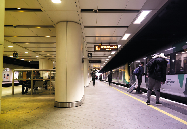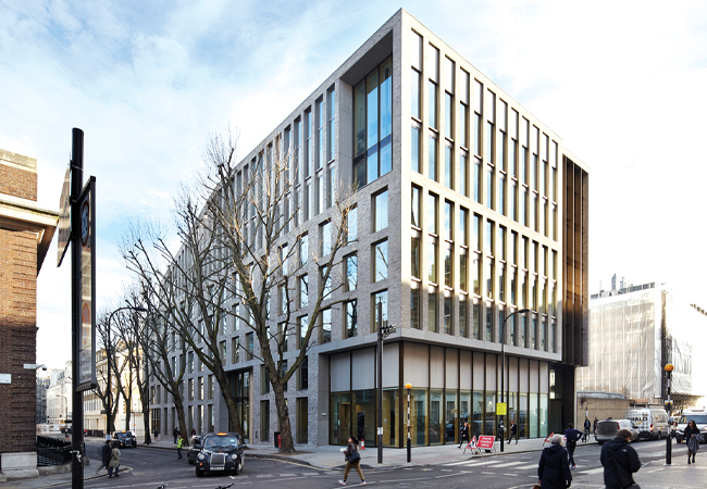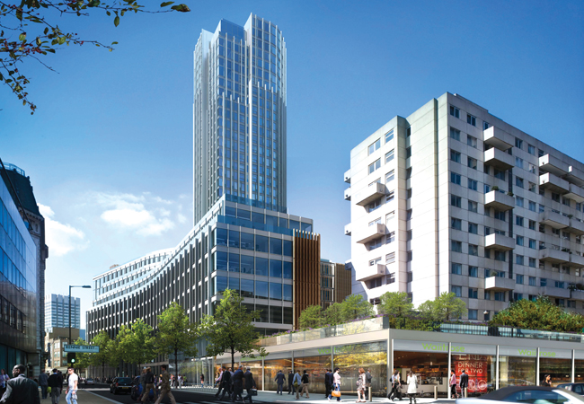
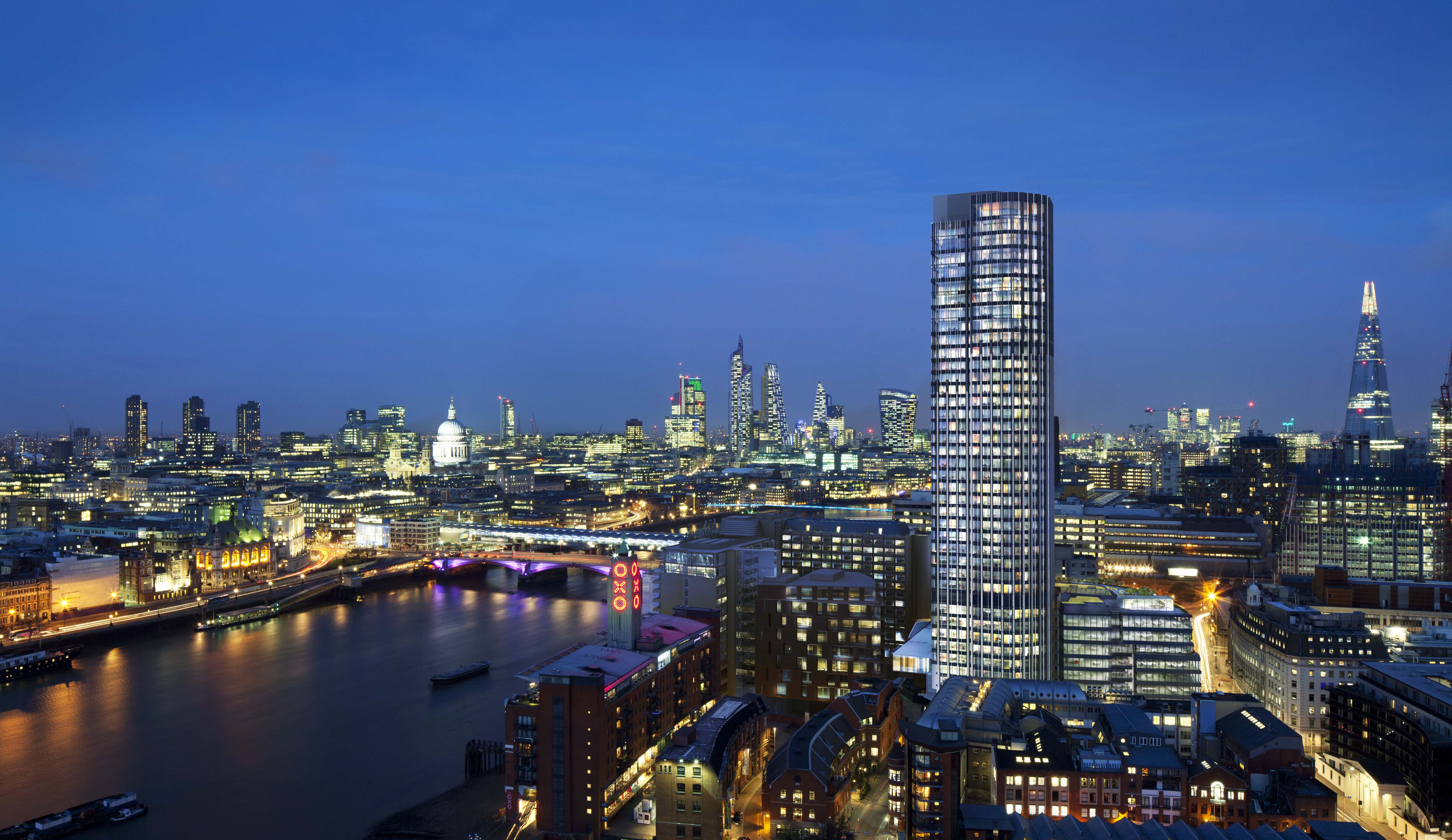
Until recently, Kings Reach Tower was a dowdy, concrete-clad, 30-storey, underused office block, set in an unremarkable area between Blackfriars and Waterloo bridges on the south bank of London’s River Thames. Now, the concrete cladding has gone, replaced by shiny floor-to-ceiling glazing. The tower has also grown in height, by 11 storeys, and the surrounding buildings have been spruced up. Even the structure’s name has changed: it now goes under the moniker ‘South Bank Tower’.
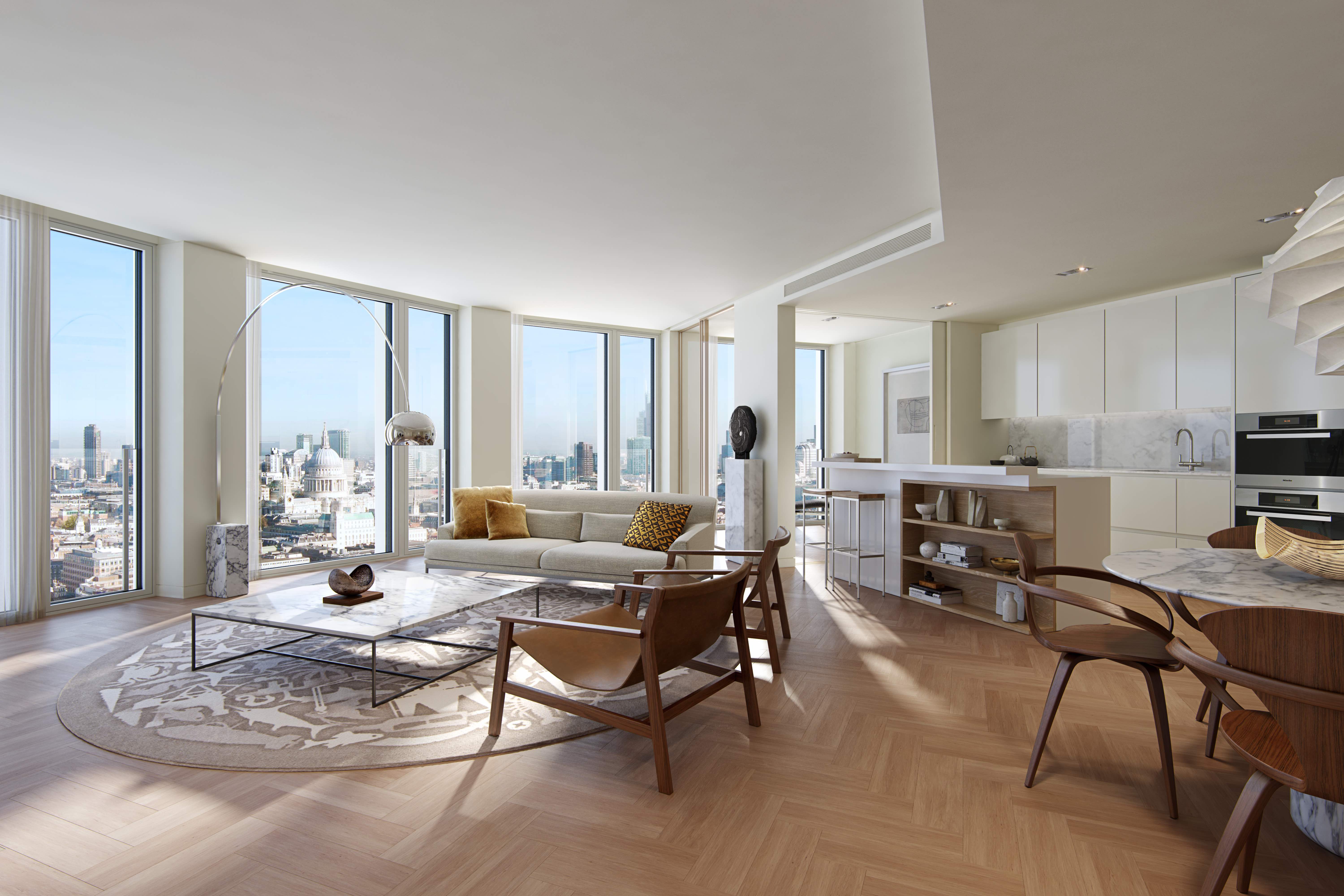
However, the most significant change is that the former office block is now a residential building. Almost all of the office space has disappeared from this new incarnation, replaced by 194 luxury apartments. Only eight floors of offices remain, occupying the tower’s lower levels, while its ground floor will house shops. The scheme is nearing completion, with main contractor Mace finalising the fit-out of the last few top-floor apartments. It is targeting Breeam Excellent for the residential domestic refurbishment, retail and offices.
A load of waffle
Key to the successful makeover from dreary 1970s office block to vibrant 21st-century mixed-use tower has been engineer Grontmij’s ability to accommodate a multitude of building services into the refurbished
concrete structure.
The tower’s transformation began with the removal of the concrete cladding and screed from all 31 floors, along with the boiler plant from the roof, to reduce the load on the foundations. This enabled the core to be extended upwards and 11 new floorplates to be cantilevered from it. Significant modifications had to be made to the existing office core, to allow the multiple access points required to create a residential floorplate.
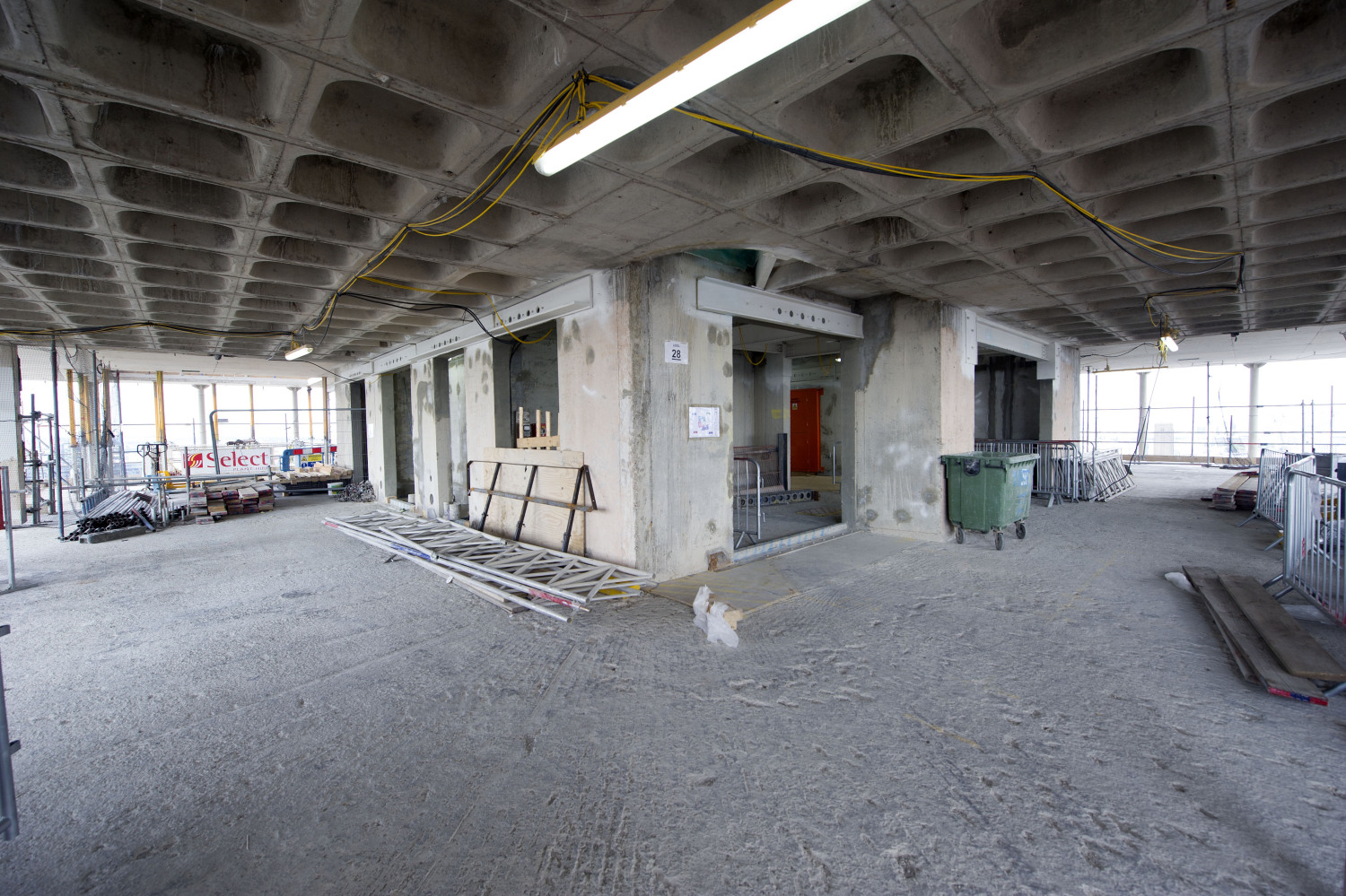
The tower’s ribbed-and-waffle slab construction made it hard to develop a drainage system for the apartments
The screed-removal works revealed the building’s existing floorplates. These were built using a concrete ribbed-and-waffle slab construction – a technique popular in the 1970s. This form of construction comprises a grid of hundreds of identical waffle pots, each resembling an inverted cake tin, assembled to form a floorplate with waffle-shaped indents on its underside. Each waffle pot measures 800 x 800mm and, at their ribbed edges, are 380mm thick – but their dished profile means they are thinner towards the centre.
The biggest challenge with this form of floor construction was that the project’s structural engineers, AKT II, would only allow penetrations through the floor slabs in the central 630 x 630mm area of each waffle pot.
Dealing with these constraints was a particular problem when it came to developing a drainage system for the apartments. ‘Without a doubt, the biggest challenge has been battling the structure to position the vertical drainage stacks to meet the architect’s aspirations,’ says Peter Hale, operations director at the scheme’s building services engineers.
In their previous incarnation, the office floors contained the plumbing for simple tea-making facilities and toilets; now the floorplates had to accommodate the plumbing for kitchens, showers, baths, basins and WCs for up to 11 apartments per floor.
The drainage design was made even more testing by the apartments having shower trays that fitted flush with the floor. This meant the trays had to be positioned very close to the HDPE drainage stacks to accommodate the fall on the waste pipe. ‘It was almost a case of putting the drainage where it could go and then working with architects KPF to design around it,’ explains Hale. As a consequence, he says, there are close to 30 drainage stacks at the base of the tower.
Cut and carve
In addition to piping drainage from the apartments, the engineers had to get heating, cooling and domestic water services to the apartments, plus cabled services such as power, satellite TV, broadband and telephones.
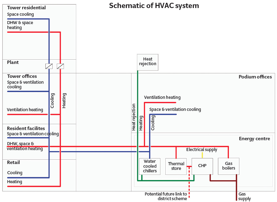
The boilers and chillers are located in the scheme’s basement energy centre, and heating and cooling pipework is routed up through the building’s central core, with distribution to individual floors and apartments. Because the tower is 160m high – and pressure in the vertical pipework increases by approximately 1bar for every 10m in height – the design incorporates heat exchangers in the tower’s Level 10 plantroom, to keep the static pressure in the heating and chilled water systems within set limits.
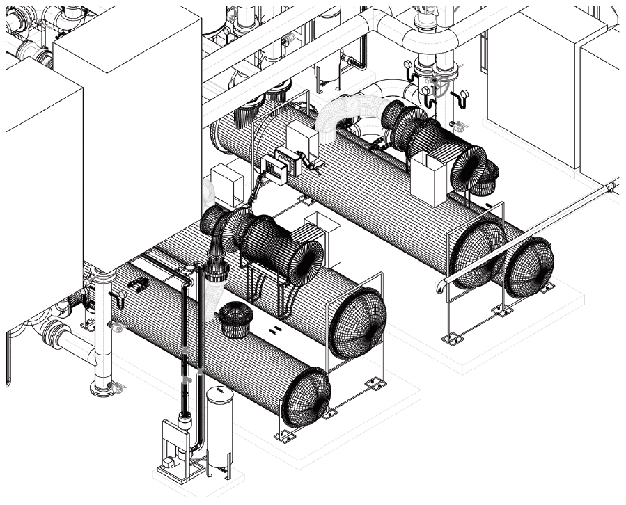
3D view of chillers in energy centre. A cooling capacity of 3,600kW is provided by water cooled centrifugal chillers, with heat rejection via roof-mounted cooling towers. The 60m³ thermal store keeps the CHP operational for longer periods of time. The stored water is used to service the heating and domestic hot water demands across the development
The heating and chilled water circuits are identical; each comprises two heat exchangers – one serving floors 11 to 26 and the other floors 27 to 41. This means that, although the heating and chilled water riser pipework serving the upper floors is at relatively high pressure in the riser, the higher pressure is confined to the riser pipework because the system is not serving apartments below Level 26.
To accommodate the new pipework, the core had to be adapted using what Hale describes as a ‘cut and carve’ technique. This involved a significant number of 3D models, working closely with contractor Mace MEP, and detailed on-site surveys. ‘The 3D modelling was useful in helping to get the builder’s work right to ensure that the holes drilled in the structural core were in precisely the right position – too many holes, or holes drilled in the wrong position, would have weakened the structure,’ Hale explains.
These works were done well in advance of the apartment internal coordination, so aspects of the apartment services design were vastly accelerated. A template approach was developed, whereby the structural modifications came with pre-coordinated service entry points cut into the steelwork before it came to site. This was used to set out the penetrations through the concrete wall.
From the core, the services are distributed above the ceiling of the circulation corridor before entering the apartments above their front doors. Once in an apartment, the pipes are routed straight to the utility cupboard. ‘We try to site the cupboard as close to the door as possible,’ says Hale. Ed Moseley, design director for the structural engineers, adds: ‘The apartment servicing strategies were heavily constrained by the existing structure. The team worked together to accelerate this coordination and enable it to be incorporated into the demolition strategy, well in advance of any detailed layouts. Principles established at this stage then had to be carried through the detailed design of the apartment layouts.’
The utility cupboard contains a heat interface unit (HIU). In individual apartments, this enables hot water to be generated locally, or by a calorifier in the case of the bigger units. The HIU steps down the heating mains temperature to enable it to serve the apartment’s underfloor heating system. This is hidden beneath a false floor, where it is fitted with metal heat-spreader plates to distribute warmth effectively in the absence of a floor screed.
Cooling for the apartments is via fan coil units (FCUs) located in the ceiling void. Typically, the apartments have one FCU in the bedroom and one or two FCUs in the living room, depending on the size of the apartment. The FCUs are not fitted with a heating coil; it was decided that underfloor heating – which distributes heat more evenly – was a more suitable form of heating for the apartments than warm air from the FCU, and it offered a more comfortable climate.
In their previous incarnation, the office floors contained the plumbing for simple tea-making facilities and toilets; now the floorplates had to accommodate the plumbing for kitchens, showers, baths, basins and WCs for up to 11 apartments per floor
Compared with the apartments, servicing the tower’s office floors was relatively simple. Again, these are supplied with heating, cooling and domestic water from the core risers. Designed as a shell-and-core scheme, the office floors are currently being fitted out with a four-pipe fan coil system.
The core also houses the lifts, which were replaced during the tower’s transformation and additional ones installed. ‘With so many high-end apartments, lift traffic analysis was important, because people don’t expect to have to wait long for a lift,’ says Hale. A new bank of lifts was added to the outside of the tower to serve the offices; these have a separate reception, on the opposite side to the residential entrance.
Sectional completion
The handover strategy was a key aspect of the construction methodology and sequencing of works. It required multiple work streams to be engaged simultaneously, digging basements while the upper levels of the tower were under construction and the apartments on the existing floors were being fitted out. The design programme was being adapted continually to reflect this.
‘A key driver, early on, was to hand over sections of the building in stages,’ says Hale. The main stages were: residential floors 11-19; residential 20-29; the tower offices and some of the retail; and, finally, the remainder of the retail and apartments. ‘This could only be achieved by starting the design with sectional completion in mind from the outset, which included planning how the scheme would be commissioned,’ says Hale. The handovers were managed by fitting heat exchangers in strategic locations on the individual services.
The real challenge with the sectional handovers, says Hale, was the fire safety, and satisfying Building Control and the London Fire Brigade that it was safe for people to occupy the building while some of the areas were still undergoing a fit-out. All fire-detection systems had to be in place and all sprinklers connected, while a safe route out of the building for residents and construction personnel had to be maintained at all times. Fire brigade access also had to be unimpeded, the fire control room had to be up and running, and the fire-fighting lifts working.
The first sectional handover was the energy centre, housed in the extensive basement. This was originally single-storey but, during the redevelopment, the basement was excavated to form a second subterranean storey for the new plantroom, while the upper level formed the residents’ car park.
The energy centre includes a 535kW combined heat and power (CHP) plant, sized for a base space-heating load and domestic hot water demand. In addition, it houses five 3750kW modular boilers, each comprising three modules. ‘The boilers had to have a good turndown to deliver heat as soon as the first sections were handed over,’ says Hale. ‘Pre-mixed gas-fired boilers operate more efficiently at low loads, so we have programmed the building management system (BMS) to bring the boilers on and off, to ensure they run at an optimised efficiency.’
Project team
Client:CIT
Architect: KPF
M&E constulant: Sweco
Main contractor and M&E contractor: Mace
Structural engineer: AKT II
South Bank Tower is part of a larger development, which includes an adjacent, eight-storey, 3,000m2, T-shaped podium office building, which is also being reconfigured and refurbished under this scheme. As well as providing heat to the tower and adjoining office podium, the CHP supplies two mid-rise apartment blocks, Rennie Court and River Court, to help increase its run-time.
‘We did a lot of detailed thermal modelling with IES software to get the development’s overall load profile correct and then, from that, to determine the CHP base load,’ says Hale. The CHP was not brought online until March 2016, close to the scheme’s completion. ‘CHPs don’t operate effectively when the output is significantly modulated, and they should not be turned on and off on a frequent basis,’ says Hale.
Most plant was prefabricated and brought to the site on skids by the services contractor. ‘The main plantroom was populated with plant in about 21 days,’ says Hale. All the risers and main horizontal pipework distribution runs in the tower were also prefabricated. This sped up commissioning because plant was pre-commissioned before delivery and the BMS was pre-programmed.
But the benefit in a busy market of off-site fabrication is not the only thing this high-spec residential conversion has highlighted. Project teams need to have a deep understanding of their site, phasing needs to be considered from day one – and drainage is king!